7 cable entry, 8 ethernet connections – SMA MLX Series User Manual
Page 18
On the AC cable, strip insulation on all 4 wires. The
protective earth wire (PE) must be longer than the mains
wires. See Illustration 2.17.
1.
Verify that the inverter rating matches the grid.
2.
Ensure that main circuit breaker is released, and
take precautions to prevent connection.
3.
Open the front cover.
4.
Insert the cable through the AC gland to the
terminal blocks.
5.
Connect the 3 mains wires (L1, L2, L3) and the PE
wire to the terminal block with the respective
markings. The PE wire is marked with the symbol
shown in Illustration 2.18.
6.
Optional: Make an extra PE connection at the
secondary PE earthing points using the external
equipment grounding bolt delivered with the
inverter. See Illustration 5.2.
7.
All wires must be properly fastened with the
correct torque. See 5.5 Torque Specifications.
Illustration 2.18 Protective Earth Symbol
2.7 Cable
Entry
Options for cable entry
•
Cable glands (premounted), or
•
2-inch conduit adapters (supplied in accessories
bag)
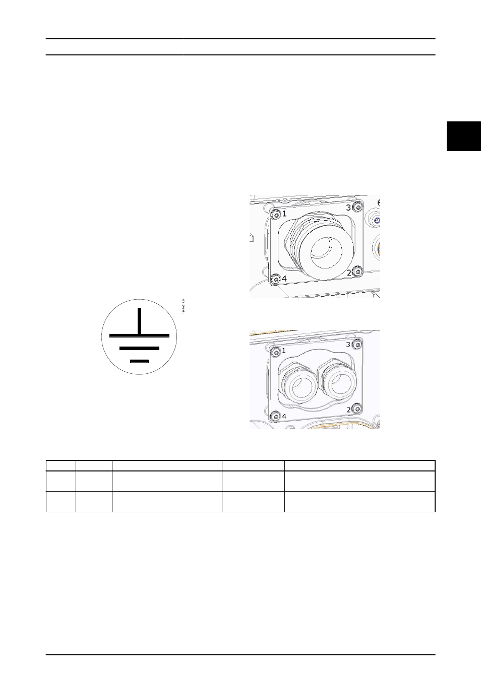
If changing to the 2-inch conduit adapters, ensure to
tighten the screws in the order shown in Illustration 2.19
and Illustration 2.20. First tighten all screws with 0.75 Nm
(6.5 in-lbf) and then 1.5 Nm (13 in-lbf).
Illustration 2.19 AC Mounting Bracket
Illustration 2.20 DC Mounting Bracket
Terminal Range
1)
Max. conductor temperature rating
Conductor material
Cable jacket diameter with supplied cable gland
AC
16-95 mm
2
6-4/0 AWG
90 ºC
Al/Cu
37-44 mm
PV
16-95 mm
2
6-4/0 AWG
90 ºC
Al/Cu
14-21 mm
Table 2.1 Acceptable Conductor Sizes
1)
Always observe current capacity of cables used.
2.8 Ethernet
Connections
Before connecting Ethernet cables, refer to the
requirements in 5.8 Ethernet Connections.
Procedure:
1.
Do not remove the RJ-45 connector on the
Ethernet cable.
2.
Run the cables through the base of the inverter
via cable glands. See Illustration 2.21.
3.
Cut slice in rubber grummet. Place the grummet
in the gland to ensure proper seal.
4.
Plug into the Ethernet connector.
Installation
L00410644-01_2q / Rev. date: 2014-06-02
17
2
2