HEIDENHAIN iTNC 530 (340 422) ISO programming User Manual
Page 55
HEIDENHAIN iTNC 530
55
2.4 D
a
tu
m
Set
ting
(With
out a 3
-D T
ouc
h
Pr
ob
e)
Saving the datums in the preset table
The preset table has the name PRESET.PR, and is saved in the
directory TNC:\. PRESET.PR is editable only in the Manual and El.
Handwheel
modes. In the Programming and Editing mode you can only
read the table, not edit it.
There are several methods for saving datums and/or basic rotations in
the preset table:
n
Through probing cycles in the Manual or El. Handwheel modes (see
User’s Manual, Touch Probe Cycles, Chapter 2)
n
Through the probing cycles 400 to 402 and 410 to 419 in automatic
mode (see User’s Manual, Touch Probe Cycles, Chapter 3)
n
By adopting the current datum, which you set manually with the axis
keys
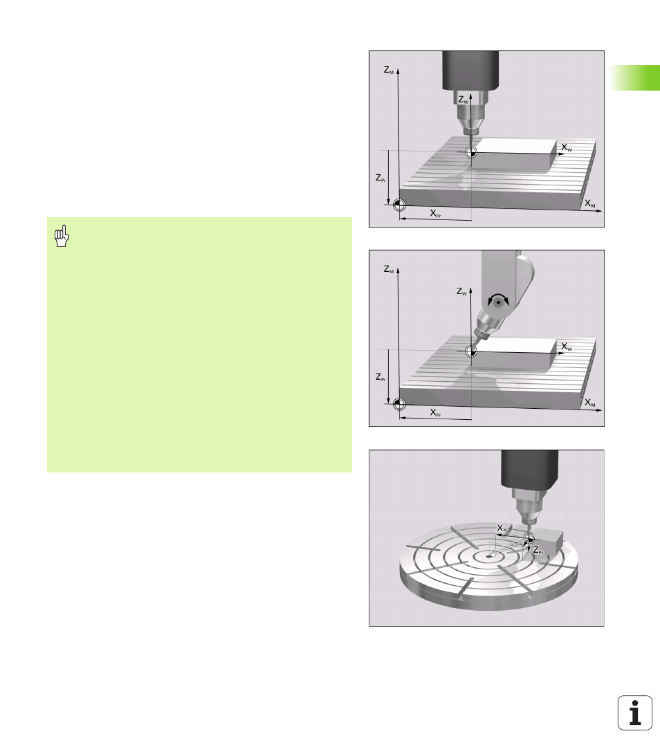
Explanation of values saved in the preset table
n
Simple machine with three axes without tilting device
The TNC saves in the preset table the distance from the workpiece
datum to the reference point (including algebraic sign, see figure at
upper right)
n
Machine with swivel head
The TNC saves in the preset table the distance from the workpiece
datum to the reference point (including algebraic sign, see figure at
center right)
n
Machine with rotary table
The TNC saves in the preset table the distance from the workpiece
datum to the center of the rotary table (including algebraic sign, see
figure at lower right)
Manual entry of values in the preset table is allowed only
if there are no tilting devices on your machine. An
exception to this rule is the entry of basic rotations in the
ROT
column. The reason is that the TNC compensates the
geometry of the tilting device when it saves values in the
preset table.
When setting a datum, the TNC checks whether the
position of the tilting axes match the corresponding
values of the 3D ROT menu (depending on Machine
Parameter 7500 bit 5). Therefore:
n
If the “Tilt working plane” function is not active, the
position displays for the rotary axes must = 0° (zero the
rotary axes if necessary).
n
If the “Tilt working plane” function is active, the
position displays for the rotary axes must match the
angles entered in the 3D ROT menu.
The machine manufacturer can lock any lines in the preset
table in order to place fixed datums there (e.g. a center
point for a rotary table). Such lines in the preset table are
shown in a different color (default: red).