HEIDENHAIN iTNC 530 (340 422) ISO programming User Manual
Page 292
292
8 Programming: Cycles
8.4 Cy
cles f
o
r Mil
ling P
o
c
k
e
ts, St
ud
s an
d Slo
ts
U
U
U
U
Machining operation (0/1/2)
Q215: Define the
machining operation:
0: Roughing and finishing
1: Only roughing
2: Only finishing
Side finishing and floor finishing are only executed if
the finishing allowances (Q368, Q369) have been
defined.
U
U
U
U
Slot length
Q218 (value parallel to the reference axis
of the working plane): Enter the length of the slot
U
U
U
U
Slot width
Q219 (value parallel to the secondary axis
of the working plane): Enter the slot width. If you
enter a slot width that equals the tool diameter, the
TNC will carry out the roughing process only (slot
milling).
U
U
U
U
Finishing allowance for side
Q368 (incremental
value): Finishing allowance in the working plane.
U
U
U
U
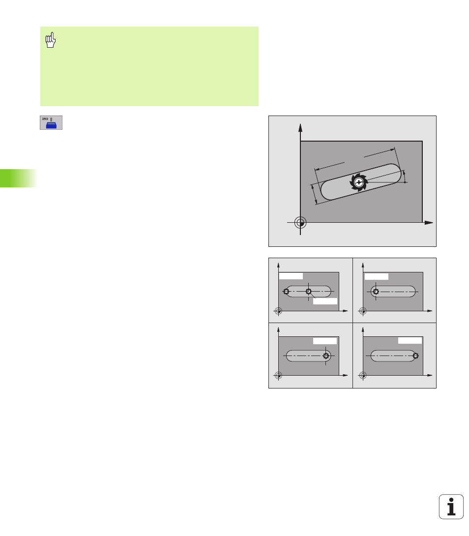
Angle of rotation
Q224 (absolute): Angle by which
the entire slot is rotated. The center of rotation is the
position at which the tool is located when the cycle is
called.
U
U
U
U
Slot position (0/1/2/3/4)
Q367: Position of the slot
in reference to the position of the tool when the cycle
is called (see figure at center right):
0: Tool position = Center of slot
1: Tool position = Left end of slot
2: Tool position = Center of left slot circle
3: Tool position = Center of right slot circle
4: Tool position = Right end of slot
U
U
U
U
Feed rate for milling
Q207: Traversing speed of the
tool in mm/min while milling.
U
U
U
U
Climb or up-cut
Q351: Type of milling operation with
M03.
+1 = climb milling
–1 = up-cut milling
Enter in MP7441 bit 2 whether the TNC should output an
error message (bit 2=1) or not (bit 2=0) if a positive depth
is entered.
Danger of collision!
Keep in mind that the TNC reverses the calculation for pre-
positioning when a positive depth is entered. This
means that the tool moves at rapid traverse in the tool axis
at safety clearance below the workpiece surface!
X
Y
Q219
Q218
Q224
X
Y
X
Y
X
Y
X
Y
Q367=0
Q367=1
Q367=2
Q367=3
Q367=4