Working plane (cycle g80), 1 0 coo rdi nat e t rans for m a ti on cy cle s – HEIDENHAIN iTNC 530 (340 422) ISO programming User Manual
Page 389
HEIDENHAIN iTNC 530
389
8.1
0
Coo
rdi
nat
e
T
rans
for
m
a
ti
on Cy
cle
s
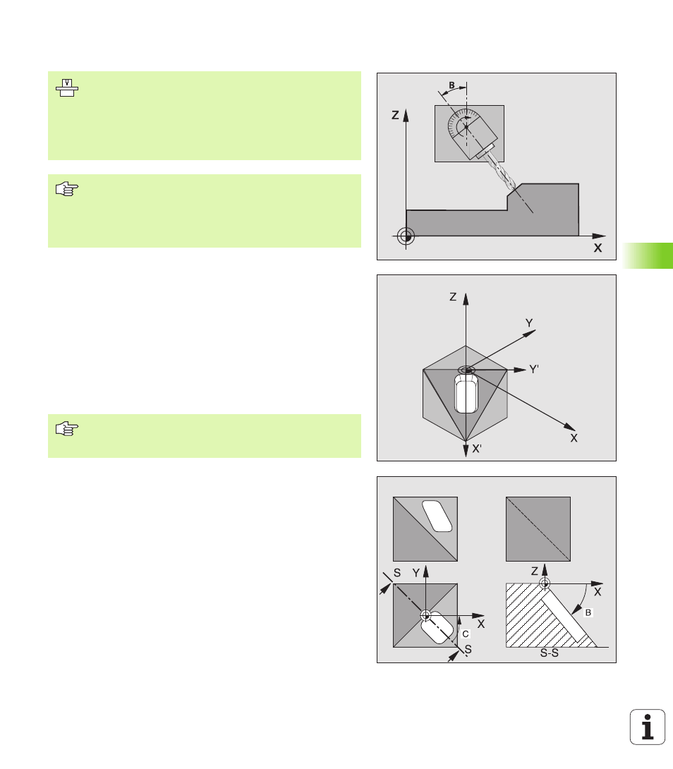
WORKING PLANE (Cycle G80)
Effect
In Cycle G80 you define the position of the working plane—i.e. the
position of the tool axis referenced to the machine coordinate
system—by entering tilt angles. There are two ways to determine the
position of the working plane:
n
Enter the position of the tilting axes directly.
n
Describe the position of the working plane using up to 3 rotations
(spatial angle) of the machine-referenced coordinate system. The
required spatial angle can be calculated by cutting a perpendicular
line through the tilted working plane and considering it from the axis
around which you wish to tilt. With two spatial angles, every tool
position in space can be defined exactly.
If you program the position of the working plane via spatial angles, the
TNC will calculate the required angle positions of the tilted axes
automatically and will store these in the parameters Q120 (A axis) to
Q122 (C axis). If two solutions are possible, the TNC will choose the
shorter path from the zero position of the rotary axes.
The axes are always rotated in the same sequence for calculating the
tilt of the plane: The TNC first rotates the A axis, then the B axis, and
finally the C axis.
Cycle 19 becomes effective as soon as it is defined in the program. As
soon as you move an axis in the tilted system, the compensation for
this specific axis is activated. You must move all axes to activate
compensation for all axes.
The functions for tilting the working plane are interfaced to
the TNC and the machine tool by the machine tool builder.
With some swivel heads and tilting tables, the machine
tool builder determines whether the entered angles are
interpreted as coordinates of the rotary axes or as
mathematical angles of a tilted plane. Refer to your
machine manual.
The working plane is always tilted around the active
datum.
For fundamentals, see “Tilting the Working Plane
(Software Option 1),” page 59. Please read this section
completely.
Note that the position of the tilted coordinate system, and
therefore also all movement in the tilted system, are
dependent on your description of the tilted plane.