3 basic contour elements, Starting point of turning contour g0-geo, Machining attributes for form elements – HEIDENHAIN SW 54843x-02 DIN Programming User Manual
Page 193
HEIDENHAIN MANUALplus 620, CNC PILOT 640
193
4.3 Basic cont
our elements
4.3 Basic contour elements
Starting point of turning contour G0-Geo
G0 defines the starting point of a turning contour.
Machining attributes for form elements
All the basic contour elements contain the chamfer/rounding form
element (BR). You can define machining attributes for this form
element and for all the other form elements (recesses, undercuts).
Example: G0-Geo
. . .
FINISHED PART
N2 G0 X30 Z0 [starting point of contour]
N3 G1 X50 BR-2
N4 G1 Z-40
N5 G1 X65
N6 G1 Z-70
. . .
Parameters
X
Contour starting point (diameter value)
Z
Contour starting point
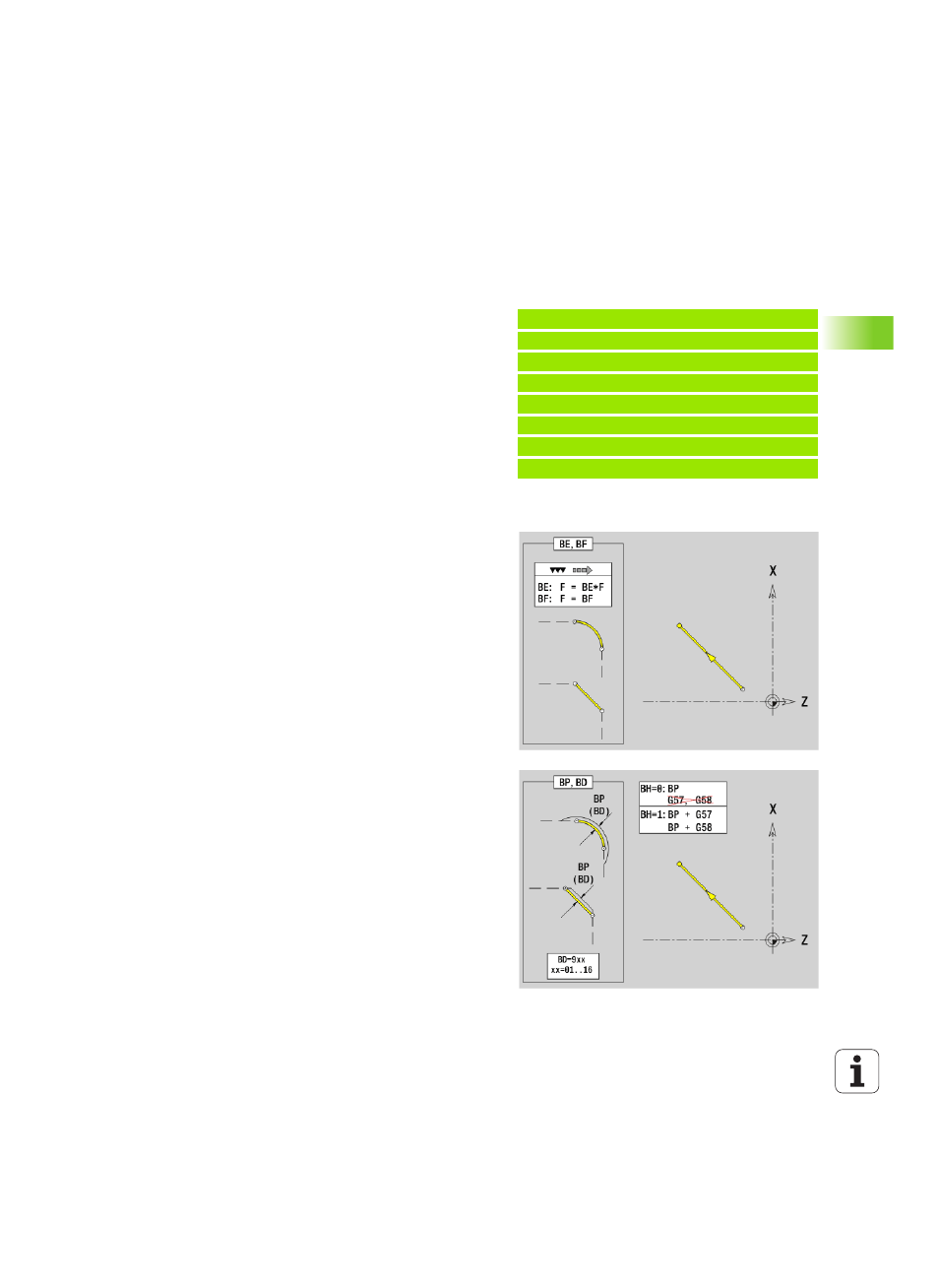
Parameters
BE
Special feed factor for the chamfer/rounding arc during the
finishing cycle (default: 1)
Special feed rate = active feed rate * BE
BF
Special feed rate for the chamfer/rounding arc during the
finishing cycle (default: no special feed rate)
BD
Additive compensation number for the chamfer/rounding arc
(901-916)
BP
Equidistant oversize (at constant distance) for the chamfer/
rounding arc
BH
Type of oversize for the chamfer/rounding arc
0: Absolute oversize
1: Additive oversize