Track configuration examples, Network requirements, Configuration procedure – H3C Technologies H3C S7500E Series Switches User Manual
Page 189

12-8
Track Configuration Examples
VRRP-Track-NQA Collaboration Configuration Example (The Master Monitors the
Uplink)
Network requirements
z
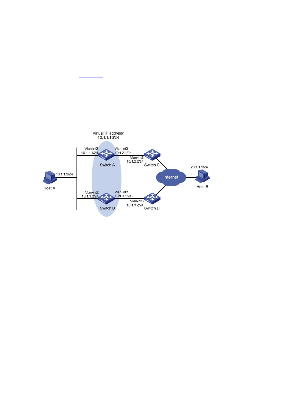
As shown in
, Host A needs to access Host B on the Internet. The default gateway of
Host A is 10.1.1.10/24.
z
Switch A and Switch B belong to VRRP group 1, whose virtual IP address is 10.1.1.10.
z
When Switch A works normally, packets from Host A to Host B are forwarded through Switch A.
When VRRP finds that there is a fault on the uplink of Switch A through NQA, packets from Host
A to Host B are forwarded through Switch B.
Figure 12-2 Network diagram for VRRP-Track-NQA collaboration configuration
Configuration procedure
1) Create VLANs, and assign corresponding ports to the VLANs, and configure the IP address of
each VLAN interface as shown in Figure 12-2. The configuration procedure is omitted.
2) Configure an NQA test group on Switch A.
# Create an NQA test group with the administrator name admin and the operation tag test.
[SwitchA] nqa entry admin test
# Configure the test type as ICMP-echo.
[SwitchA-nqa-admin-test] type icmp-echo
# Configure the destination address as 10.1.2.2.
[SwitchA-nqa-admin-test-icmp-echo] destination ip 10.1.2.2
# Set the test frequency to 100 ms.
[SwitchA-nqa-admin-test-icmp-echo] frequency 100
# Configure reaction entry 1, specifying that five consecutive probe failures trigger the Track-NQA
collaboration.
[SwitchA-nqa-admin-test-icmp-echo] reaction 1 checked-element probe-fail threshold-type
consecutive 5 action-type trigger-only
[SwitchA-nqa-admin-test-icmp-echo] quit
# Start NQA probes.
