Pim-sm non-scoped zone configuration example, Network requirements – H3C Technologies H3C S12500-X Series Switches User Manual
Page 101
91
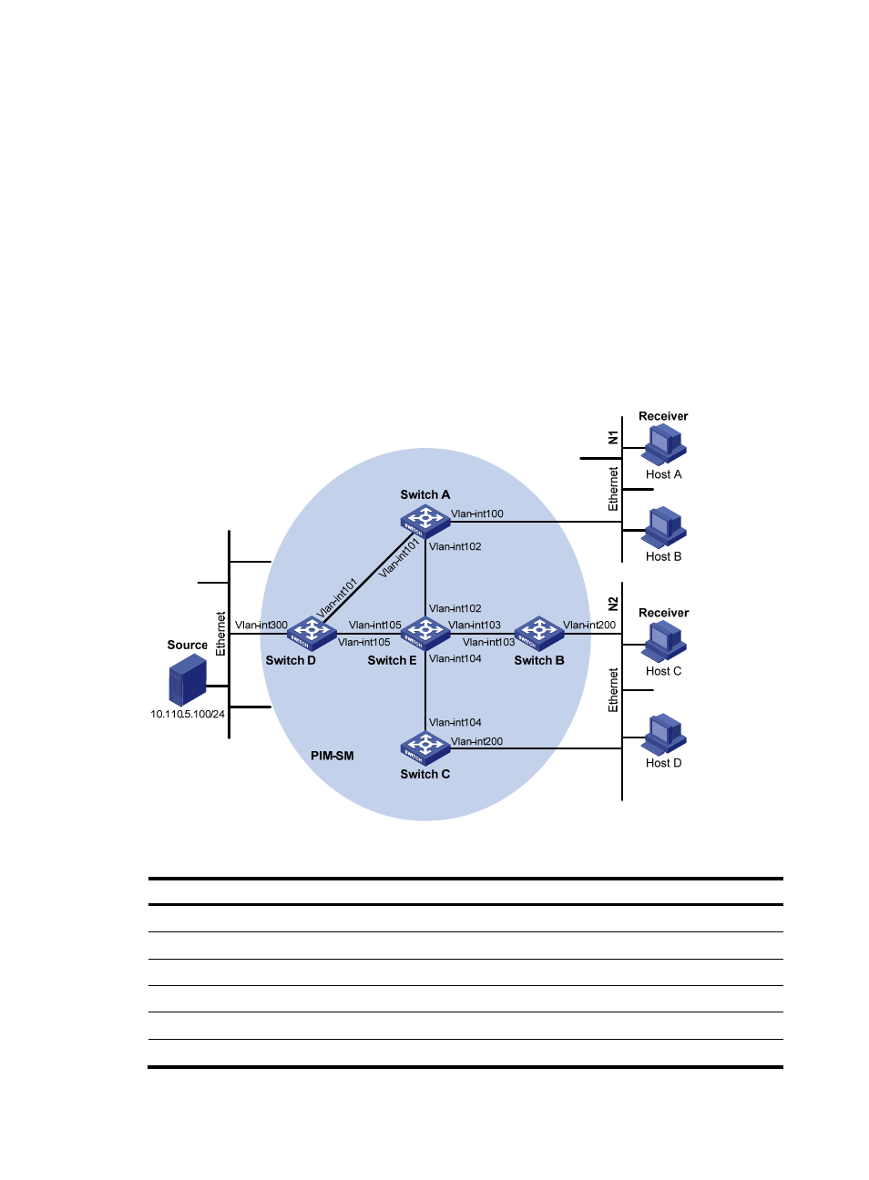
PIM-SM non-scoped zone configuration example
Network requirements
As shown in
:
•
VOD streams are sent to receiver hosts in multicast. The receivers of different subnets form stub
networks, and at least one receiver host exist in each stub network. The entire PIM-SM domain
contains only one BSR.
•
Host A and Host C are multicast receivers in two stub networks N1 and N2.
•
Both VLAN-interface 105 on Switch D and VLAN-interface 102 on Switch E act as C-BSRs and C-RPs.
The C-BSR on Switch E has a higher priority. The C-RPs are designated to the multicast group range
225.1.1.0/24. Modify the hash mask length to map the multicast group range to the two C-RPs.
•
IGMPv2 runs between Switch A and N1, and between Switch B, Switch C, and N2.
Figure 33 Network diagram
Table 7 Interface and IP address assignment
Device Interface
IP address
Switch A
VLAN-interface 100
10.110.1.1/24
Switch A
VLAN-interface 101
192.168.1.1/24
Switch A
VLAN-interface 102
192.168.9.1/24
Switch B
VLAN-interface 200
10.110.2.1/24
Switch B
VLAN-interface 103
192.168.2.1/24
Switch C
VLAN-interface 200
10.110.2.2/24
- H3C S9800 Series Switches H3C S5560 Series Switches H3C S5130 Series Switches H3C S5120 Series Switches H3C S12500 Series Switches H3C SR8800 H3C SR6600-X H3C SR6600 H3C WX6000 Series Access Controllers H3C WX5000 Series Access Controllers H3C WX3000 Series Unified Switches H3C LSWM1WCM10 Access Controller Module H3C LSWM1WCM20 Access Controller Module H3C LSQM1WCMB0 Access Controller Module H3C LSRM1WCM2A1 Access Controller Module H3C LSBM1WCM2A0 Access Controller Module