Welltech SPCI2S Intel NetStructure SS7 Boards User Manual
Page 84
SS7 Programmer’s Manual for SPCI2, SPCI4 and CPM8 Issue 2
Page 84
5.5.3 Clock Event Indication
Synopsis:
Message issued by the board to indicate on-board clocking related events.
Message Format:
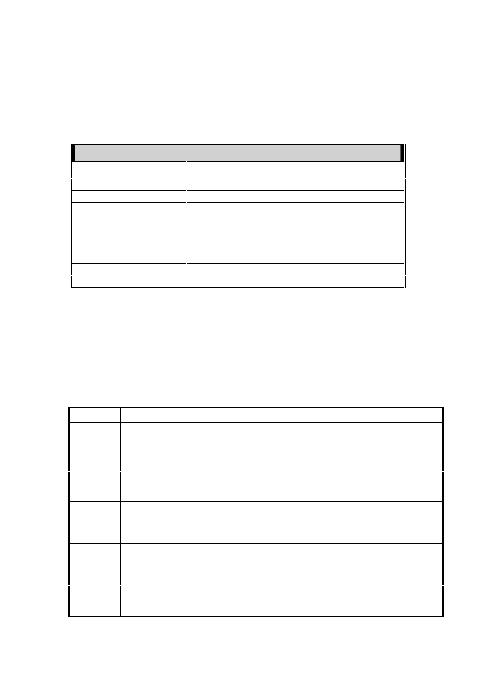
MESSAGE HEADER
FIELD NAME
MEANING
type MVD_MSG_CLK_IND
(0x0e23)
id
0
src MVD_TASK_ID
dst 0xdf
rsp_req
0
hclass
0
status event_id
(see below)
err_info
Reserved for future use
len
0
Description:
This message is issued by the board to indicate events within the on-board
clocking circuitry.
Parameter Description:
event_id This field specifies the event that caused the indication to be generated:
event_id Description
1
PLL entered hold-over mode
Issued by boards acting as primary or secondary clock master when its nominated
clock reference becomes unavailable. The phase-locked-loop starts operating in
“hold-over” mode, continuing to generate an on-board clock at the same frequency as
the last valid reference signal.
2
PLL left hold-over mode
The nominated clock reference for a primary or secondary master board has become
available and the is now being used as the input to the board’s clock circuitry.
3
CT bus clock set A fail
The CT bus clock set A signals are not being correctly driven.
4
CT bus clock set A recover
The CT bus clock set A signals are being driven.
5
CT bus clock set B fail
The CT bus clock set B signals are not being correctly driven,
6
CT bus clock set B recover
The CT bus clock set B signals are being driven.
7
Master clock changeover
The card issuing this indication has automatically changed from secondary master to
primary master role for the clock set it was configured to drive.