Your hal tester – Seaward ClareHAL User Manual
Page 130
129
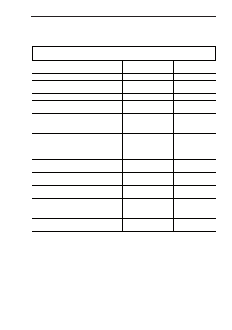
Hal 104 Control Ports
19 Way Connector
Connector
Position
Signal
Wire Style
H104 Position
A
0V
Brown 16s
CN6 PIN 1
B
Analogue 1
Red 16s
CN6 PIN 2
C
Analogue 2
Orange 16s
CN6 PIN 3
D
Analogue 3
Yellow 16s
CN6 PIN 4
E
Analogue 4
Green 16s
CN6 PIN 5
F
Analogue 5
Blue 16s
CN6 PIN 6
G
Analogue 6
Violet 16s
CN6 PIN 7
H
Analogue 7
Grey 16s
CN6 PIN 8
J
Analogue 8
White 16s
CN6 PIN 9
V
0V
Black/Orange 16s Earth Stud
(M4 ring)
K
START
Black 16s
Solder to Start
Button
L
START
Brown/Grey 16s
Solder to Start
Button
M
STOP
Red/Black 16s
Solder to Stop
Button
N
STOP
Orange/Violet 16s Solder to Stop
Button
P Change-over
Drive
Yellow/White 16s
Aux Switch
COM
R
STATUS COM Green/Grey 16s
J31 PIN 3
S
STATUS PASS Purple/Red 16s
J31 PIN 1
T
STATUS FAIL
Grey/Red 16s
J31 PIN 2
U Power
Drive
White/Orange
16s
RL1 Coil PIN
1
Your HAL tester