Your hal tester – Seaward ClareHAL User Manual
Page 126
125
Addendum Notes
HAL Series Remote Connection for Pass/Fail
Indications and Remote Fault Reset
The HAL Tester can be ordered with this additional option. This option
will appear as two additional rear sockets for remote ‘Pass/Fail Status’
and for ‘Remote Fault Reset and Start’.
Mode
Contacts
Status
Indicators
The M
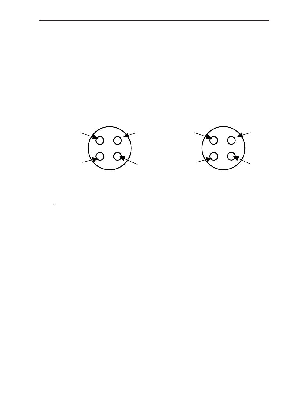
Mode Contacts SOCKET is for externally clearing the fault by
remotely closing the internal poles of the Hal front panel RED and
GREEN buttons – by using an isolated external closing contact.
Pin A – GREEN BUTTON N/O
Pin B – GREEN BUTTON COMMON
Pin C – RED BUTTON N/O
Pin D – RED BUTTON COMMON
The S
Status Indicator PLUG is for remote connection to the test
‘Pass/Fail Status’
Pin A – COMMON
Pin B – PASS
Pin C – FAIL
Pin D – NOT USED
The Pass/Fail Status connections are unpowered and require an
external supply voltage (recommended 12/24Vdc) to operate. For 24V
operation use 2K resistors – see diagram below for typical PLC
interface:
C
O
M
P
A
S S
F
A IL
RE MOT E
S TAT US IND ICAT ION
RE MOT E
F AUL T RE SET
B
C
A
R
E
F E
R
T O
U
S E
R
M A
N
U A
L
F O
R
D E
T
A IL
S
C
O
M
P
A
S S
F
A IL
RE MOT E
S TAT US IND ICAT ION
RE MOT E
F AUL T RE SET
B
C
A
R
E
F E
R
T O
U
S E
R
M A
N
U A
L
F O
R
D E
T
A IL
S
A
D
B
A
B
C
D
Your HAL tester