Set up base location, Figure 33: rtk base control, Figure 34: base location – user input – NavCom StarUtil Rev.G User Manual
Page 45
StarUtil User Guide – Rev. G
RTK Base Control, Unit Port Configuration, And Antenna Setup
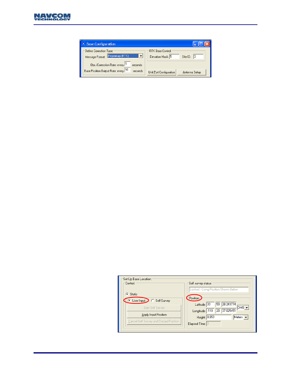
Figure 33: RTK Base Control
a will be transmitted to the rover for use in calculating positions.
de the performance of the rover.
ult base Site ID (3) or enter an ID to isolate the base and rover
must be set to the identical ID. This avoids cross talk
that may be set to the
(the default), the rover
accepts RTK corrections from any base station (see Figure 47).
Network ID
Depending on configura
Tracking
Setup window ma
PDOP
For Solution,
Various Controls That Af
ails.
10. Click the An
the antenna
Figure 13)
Set Up Base Location
11. Enter the position of the base station, manually via User Input (the default) or automatically
via Self Survey:
• User Input (the d
uth position in
Figure 34: Base Location – User Input
Refer to Figure 33 for the steps below:
9. Set the options if desired:
• Elevation Mask: Enter the cutoff vertical angle above the horizon. For any satellites
below this angle, no dat
The default recommended setting for the base receiver is 5 degrees; however,
the height of on-site obstructions will dictate this setting. Collecting poor data (i.e.
through trees) at the base will degra
• Site ID: Accept the defa
radios, if desired. The rover radio
between the rover radio and any other base radio in the area
same frequency. For multiple base stations, use a different site ID for each one. The
valid range for a site ID is 0 to 1023. If the rover Site ID is 0
Models RT-3010 & RT-3020 only (with internal radio): StarUtil provides a
option (see Figure 70). In addition to the RTK Site ID above, this
provides a second method of differentiating multiple available networks.
tion, these options on the Rover / Navigation &
y affect base station operation: Min SV’s For Solution, Max
Max RTK Age, and Tracking\Elevation Mask. Refer to the section,
fect Base Station Operation, in Chapter 3 for det
tenna Setup button, if desired, to set the appropriate bias adjustment values for
model in use (optional). The Vertical Antenna Bias window opens (see
efault):
Manually enter the known
surveyed tr
the Position section of the
window (see Figure 34).
Click the Apply Input
Position button to save the
position in NVRAM.
5-43