Measurement Computing DaqView User Manual
Page 58
In the Waveform Type box, you can select a standard function generator waveform (sine, square, triangle,
sawtooth) or a freehand drawing. In Freehand, move the mouse to the waveform window and draw a
waveform using the left mouse button.
The <Save Waves> button allows you to save the values of each displayed waveform to disk in an ASCII
format. The files created are compatible with spreadsheets and word processors, allowing you to
numerically inspect and/or alter the saved waveforms.
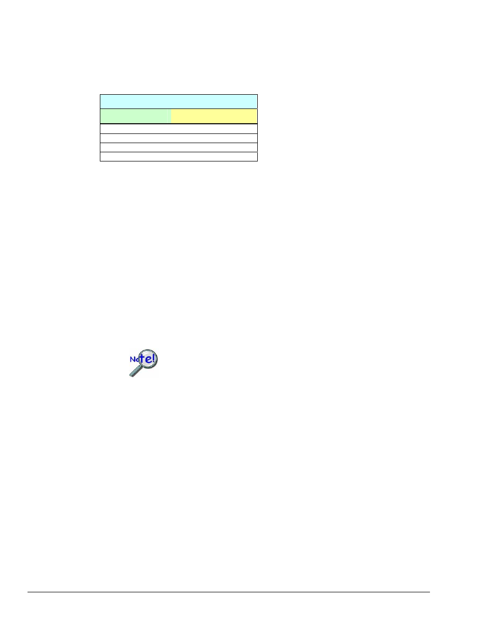
Sample Waveform File Format Examples
One Channel
Two Channels
2043
1019
300
923
In the “Two Channels” example [second
column, immediate left], the entry preceding
after
The
Updates per Channel field.
The <Copy Waves> and
data from all DAC channels. The data formats are identical to the Save and Load operations.
Waveforms can also be copied and pasted from the popup menu that is displayed when the mouse is right
clicked over the Waveform display. The waveform selected in the DAC selection list-box is the target of
the Cut or Paste. If multiple channels of data are on the clipboard, you can select the one that you want to
paste into the selected DAC channel.
The size of the memory buffer allocated for each DAC channel is determined by the number of updates
that you specify. Different Daq devices have different limits on the maximum updates that can be
specified.
You can select one of three clock sources to pace the DAC output. The three options are as follows:
•
DAC Pacer with a rate set in the Sample Update Rate field. When using the DAC pacer, the
Update Rate field controls the speed at which the DAC is updated.
If the DAC Pacer clock is selected, you must enter the update rate that
paces the DAC outputs.
•
Acq Pacer, the clock used by the analog input section of the DaqBoard. Using the Acq pacer
clock synchronizes the update of the DAC output with the analog input data collection.
•
External TTL. Update rate is controlled by the rate of the clock signal applied to the
external input pin.
The selection for the DAC channel, for which you want to create a waveform, is made in the DAC
selection listbox
. From the same listbox you can control the channel's output by clicking the checkbox on
or off. Note that of the devices that support analog output channels, some have two DACs, and will
therefore allow for only two channels to be selected; while other devices have four DACs and allow for up
to for DAC analog output channels to be selected.
In the Waveform selection box, you can select a standard function generator waveform (sine, square,
triangle, sawtooth) or an arbitrary freehand drawing. In arbitrary mode, move the mouse to the waveform
window and draw a waveform using the left mouse button. The drawn waveform will be loaded into the
channel selected in the DAC channel listbox. You can also create a waveform by right clicking the mouse
with the cursor over the waveform window. Select the waveform type from the resulting popup menu.
Repeat this process for each channel in the DAC selection listbox.
To start the waveforms playing on the DACs, click the
10-2 Waveform & Digital Pattern Output Window
888994
DaqView User’s Guide