Measurement Computing DaqView User Manual
Page 28
4-4 The Main Window
987691
DaqView & ViewXL
User’s Guide
Multi-channel
Triggering
If you have a product which supports multi-channel triggering then you should set up the
triggering for each channel in the Setpoints dialog and set the trigger channel to be the
setpoint status.
If you wish to perform an OR operation on the trigger channels -
use the “Not Equal” mode and 0 as the value.
If you wish to perform an AND operation on the channels -
use the “Equal To” mode, and use a value which represents the bit pattern corresponding to
the individual setpoint for each channel.
If there are setpoint channels which you do not want to have evaluated
the mask value can be used to ignore those channels.
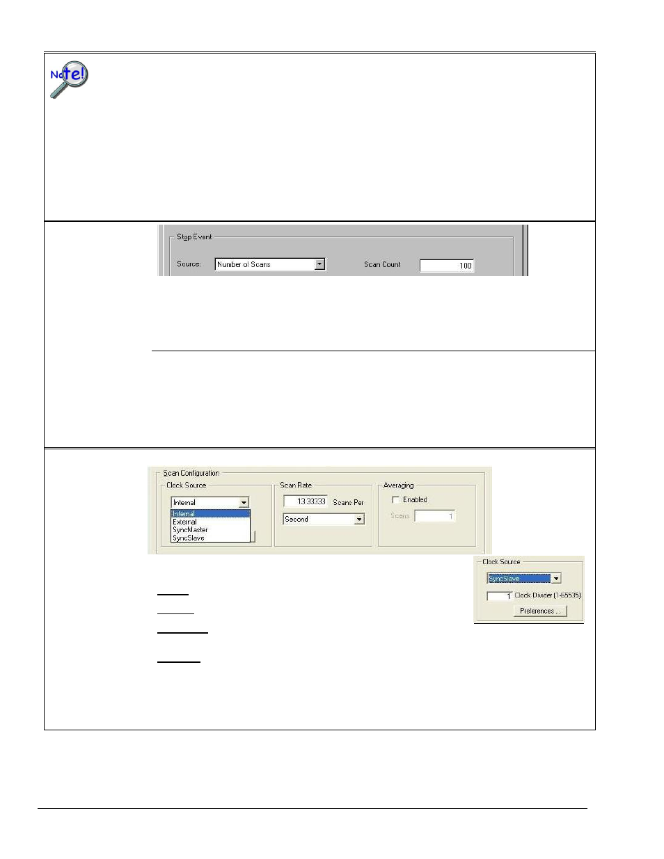
Stop Event
The Stop Event panel is used to select the event that stops the scanning, depending on the device connected.
Possible sources include:
Number of Scans - can range from 1 to 100,000,000. A scan includes all of the channels that are marked as
“On” in the Analog & Scanned Digital Inputs spreadsheet.
Key Hit
– stops acquisition when the user presses a key.
In regard to applicability
of these stop events
refer to the hardware
manual for your specific
device.
Above/Below Level
– monitors value on selected channel; stops scan when parameter is satisfied.
Rising/Falling Edge
– monitors value with hysteresis on the selected channel; stops the scan when the
parameter is satisfied.
Inside/Outside Window
– monitors upper and lower values on selected channel; stops scan when parameters
are satisfied.
Digital Pattern
– monitors 8-bit pattern on selected digital input channel; stops scan when parameters
(less/greater than or equal to/not equal to) are satisfied.
Scan Configuration
Clock Source
Drop-down list
Provides a means of choosing one of the following options:
Internal
– selects the device’s internal clock
External
– selects an external user-supplied clock
SyncMaster
– Sets the device as the Master and selects the internal pacer
clock.
(SyncMaster does not apply to all devices)
SyncSlave
– Sets the device as a Slave unit and uses the clock of a Master
device to which it is connected. In addition, when SyncSlave is selected a
Clock Divider box appears (right-side figure). The value of the divider can be
set from 1 to 65535. This sets the scan rate to a fraction of the Master rate.
The fastest rate is set by using a value of “1.” A setting of “10” would result in
a scan once every tenth clock pulse. The slowest possible setting is “65535.”
(SyncSlave does not apply to all devices)
Clock Divider
The Clock Divider only
appears when SyncSlave is
selected from the drop-down
list.
Note: The parameters identified on this and the following page cannot be altered during an acquisition.