Preassembly – Harken 948 MKIII Jib Reefing & Furling User Manual
Page 21
Preassembly
How many foils and connectors • Stringing connectors
March 2001
Unit 2.5 MKIII
11
Pin-to-Pin Headstay Length (See Pg 8)
Longueur axe à axe de l’étai (Voir Pg 8)
Bolzen-Bolzen-Mass Anzahl des Vorstages (s.S. 8)
Lunghezza perno-a-perno dello strallo (vedi p. 8)
Number 7" (178 mm) Connectors
Nombre de connecteurs de 152 mm utilisés
Anzahl benötigter Verbinder von 152 mm
Numero di estrusi da 152 mm usati
39'10" to 40'9" (12.141 m to 12.421 m)
5
40’10" to 47’9" (12.446 m to 14.554 m)
6
47’10" to 54’9" (14.580 m to 16.688 m)
7
54’10" to 61’9" (16.713 m to 18.821 m)
8
61’10" to 67’10" (18.847 m to 20.676 m)
9*
Number 7’ (2.13 m)Foils Used
Nombre de profils de 2.13 m utilisés
Anzahl benötigter Profile von 2.13 m
Numero di estrusi da 2.13 m usati
39’10" to 46’10" (12.141 m to 14.275 m)
5
46’11" to 53’10" (14.300 m to 16.408 m)
6
53’11" to 60’10" (16.434 m to 18.542 m)
7
60’11" to 67’10" (18.567 m to 20.676 m)
8*
■ How Many Connectors?
Use the chart at left to determine the proper number
of 9" (229 mm) connectors for your headstay.
Every unit uses one 11" (280 mm) bottom connector in
addition to
the number of 9" (229 mm) connectors
shown at left.
*One additional connector required; order part 899 for
rod and part 982 for wire.
■ How Many Foils?
Use the chart at left to determine the proper number of
7' (2.13 m) foils for your headstay.
The variable length top foil is cut from one of the 7'
(2.13 m) foils and is used in addition to the number of
foils shown at left.
*One additional foil required; order part 897
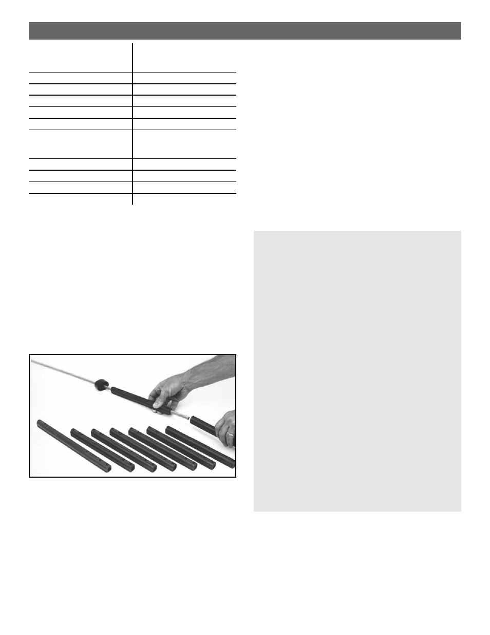
■ Stringing Connectors - Rod
Confirm connector inside diameter — .465"
(11.8 mm). See “Connector Bore”, page 3.
After the headstay has been cut to length, but before
the lower terminal is attached, the proper number of
connectors must be placed on the headstay in the cor-
rect order.
Every unit uses a top foil trim cap.
Every unit uses a number of 9" (229 mm) connetors
which varies according to the length of the headstay
and is determined by consulting the chart above.
Every unit uses one 11" (280 mm) bottom
connector
Slide the trim cap onto the stay so that the open
end faces down.
Slide the proper number of 9" (229 mm) connectors
onto the headstay.
Slide the 11" (280 mm) bottom connector onto the
headstay so that it is closest to the bottom of the
headstay.
Slide the rod adapter nosepiece onto the stay.
Have the rod coldheaded by a reputable rod ser vice
center. If you ship the rod headstay to a ser vice center
do not coil it tighter than 200 times the rod’ s diameter.
■ Wire Instructions
Confirm connector inside diameter — .53" (13.5 mm). See “Connector Bore”, page 3.
Because Norseman and Sta-Lok terminals are applied to the headstay wire after the foil is built, it is not necessar y to
place the connectors or trim cap on the wire at this time. Norseman and Sta-Lok units require the same number of
foils and connectors as shown above. Identify the parts you need and set them aside at this time.