Test 4 – mobile-to-phone path 2, Test 5 – mobile-to-phone audio path, Test 6 – non-accessed patch functions – GAI-Tronics MRTI 2000 (No. PL1877A) Microprocessor Radio Telephone Interconnect Installation & Service Manual User Manual
Page 20
Installation PL1877A
Microprocessor Radio Telephone Interconnect
12/10 14
Test 4 – Mobile-to-Phone Path 2
Test 4 is identical to Test 3 with the following exceptions. Test 4 activates the monitor output and
disables RX autoleveling. The LEDs (refer to the LED assignment diagram on page 13) display the
status of the following:
• PTT Sense Input - LED 1 (bit 7)
• PL Detect Input - LED 2 (bit 6)
• Auxiliary Carrier Detect - LED 3 (bit 5)
The 5 least significant LEDs are used to display decoded DTMF digits.
Test 5 – Mobile-to-Phone Audio Path
PTT is activated and phone audio is autoleveled and routed to the transmitter. If enhanced VOX option
is present, enhanced VOX operation is used, otherwise autoleveling is used. The UP button is used to
toggle phone line autoleveling ON or OFF. The 5 least significant LEDs (refer to the LED assignment
diagram on page 13) display a binary representation of DTMF decoded from the phone line. The most
significant LED indicates the status of phone line VOX, if the enhanced VOX option is present.
N
OTE
: A DTMF “0” is displayed as hexadecimal 10 (decimal 16) in binary.
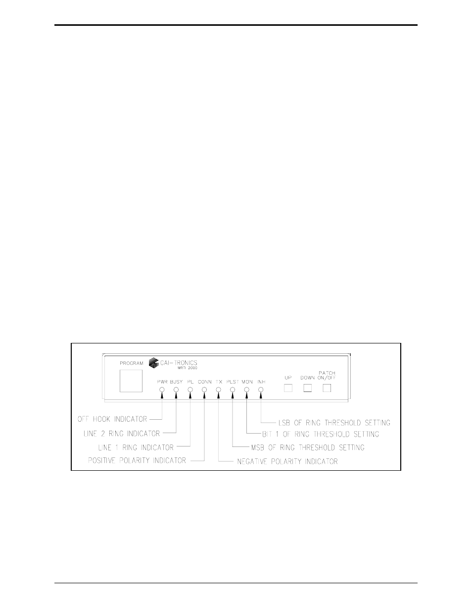
Test 6 – Non-accessed Patch Functions
The non-accessed phone line status, is represented by the LEDs. The signals displayed are:
• Off Hook Status of an Attendant Phone
• Ring Voltage
• Phone Line Current Polarity (positive, negative, none)
• Ring Threshold Setting
Refer LED assignment diagram for Test 6 below.