Flexar repeater – GAI-Tronics MRTI 2000 (No. PL1877A) Microprocessor Radio Telephone Interconnect Installation & Service Manual User Manual
Page 157
PL1877A Microprocessor Radio Telephone Interconnect
PL1877A – Radio Installation
151
12/10
FLEXAR Repeater
Install the following modifications/additions to the Flexar repeater using the supplied connector pins.
Female pins are used on J801. Wire colors specified match PL1877A cable wire colors, and, if followed,
may assist in any future service.
1. RX Detector Audio - Run a green/white wire from J801 (metering socket) pin 1 to P901 (receiver
chassis plug) pin 1 (male pin). Run another green/white wire from J901 pin 1 (female pin) on the
receiver chassis to U10 pin 6 (detector audio output).
2. PL Detect - Run a black wire from J801 pin 9 position to P901 pin 2 (male pin).
Tone PL (reed type, TRN6177 and similar) - Run another black wire from J901 pin 2 (female pin)
on the receiver chassis to U401 pin 13 on the PL deck. Locate and remove the soldered in JU401 and
install a 100k, 1/4 W resistor in its place. (Note: There are two JU401’s shown on the board
pictorial. The correct one for this function is the one in series between U401 pin 13 and Q409 base.)
This resistor allows pin 13 of U401 to swing between detectable logic levels. Remove C428 and
replace it with a 1
µF capacitor, observing polarity.
Tone PL (reedless type, TRN4273A and similar) - Run another black wire form J901 pin 2 (female
pin) on the receiver chassis to U401 pin 28 on the PL deck..
Digital PL (TRN6207A and similar)
Run another black wire from J901 pin 2 (female pin) on the receiver chassis to U301 pin 7 on the PL
deck.
3. TX PL Strip - Locate the orange/black wire running from J701 pin 10 to filter bracket terminal 10.
Cut this wire off at the filter bracket and install a male pin on the free end. Insert the pin into J801
pin 2 position. This is a spare wire that terminates at J601 on the transmitter chassis in the Flexar
housing. Run another orange/black wire from J602 pin 10 position (may already be present) to the
cathode side of CR120 on the exciter chassis.
4. TX Audio - Run a blue/white wire from the J801 pin 4 position to the previously vacated filter
bracket terminal 10. On the Repeater control board, connect a blue/white lead in series with a 1M
resistor: from J20 pin 10, clipping the resistor leads to 1/2 inch and soldering the resistor to U2 pin 9.
Use heat shrink or other “spaghetti” to insulate the wire-end of the resistor.
5. PTT - Run a white wire from the J801 pin 5 position to terminal 8 of the filter bracket.
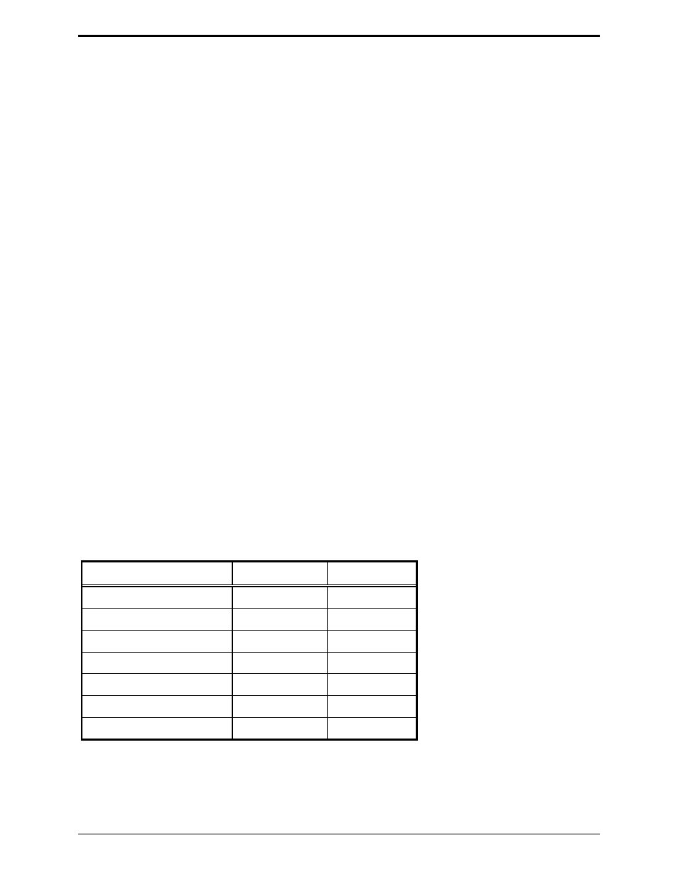
6. Install male pins on the PL1877A P1 radio cable and insert them into a plug body (not supplied -
Motorola P/N 15-80315A40) as follows:
Color Function
Plug
Pin
No.
Green/white Rec.
audio
1
Black PL
detect
9
Blue/white Transmit
audio
4
White PTT
5
Red/black
TX PL strip
2
Red, orange/black
Ground
6
Green/black, blue/black
Ground
6
This plug mates with J801.
If the PL1877A is to be dc-powered, connect the red lead in the dc power cable to P801 pin 7 and the
black lead to P801 pin 6; connect the other end of the dc power cable into the 5-pin DIN connector (DC
PWR), on the rear panel of the PL1877A. If the optional ac transformer is to used, install the ac power
connector into the 5-pin DIN connector (DC PWR), on the rear panel of the PL1877A.