GAI-Tronics MRTI 2000 (No. PL1877A) Microprocessor Radio Telephone Interconnect Installation & Service Manual User Manual
Page 152
Pl1877A – Radio Installation
PL1877A Microprocessor Radio Telephone Interconnect
12/10 146
4. Reverse Burst Disable (necessary for signal search mode only.)
Tone PL (reed type, TRN6177C and similar)
Remove the lead on the PL deck that comes from J601, pin 1 (PL on-off from hang-up box) and
solder it to Q406 base. Solder the supplied .01
µF RF decoupling capacitor between base and emitter
of Q406. Connect JU401 to HD (N
OTE
: There are two JU401’s shown on the board pictorial. The
correct one for this function is the one that grounds the emitter of Q409 when connected to pin HD).
Tone PL (reedless type) (TRN4237A and similar) Remove the lead on the PL deck that comes
from J601, pin 1 (PL on-off from hang-up box), and solder it to U401, pin 36. Remove the lead on
the PL deck that comes from J601, pin 2 (hang-up box ground), and solder it to the junction of C414
and R408 on the PL deck. Remove R421 on the PL deck (between U401, pin 7 and pin 26). Solder
the supplied diode into the JU102 holes on the main circuit board, (close to squelch control) with the
cathode toward mic PTT.
Digital PL (TRN6207A and similar) Remove the lead on the PL deck that comes from J601, pin 1
(on-off from hang-up box) and solder it to Q312 base. Connect JU302 to pin D.
The Monitor function is now via the front panel and/or desk mic monitor switch. Now, connect the
PL1877A P1 radio cable to the base station P601 connector as follows, using the supplied male connector
pins, as applicable.
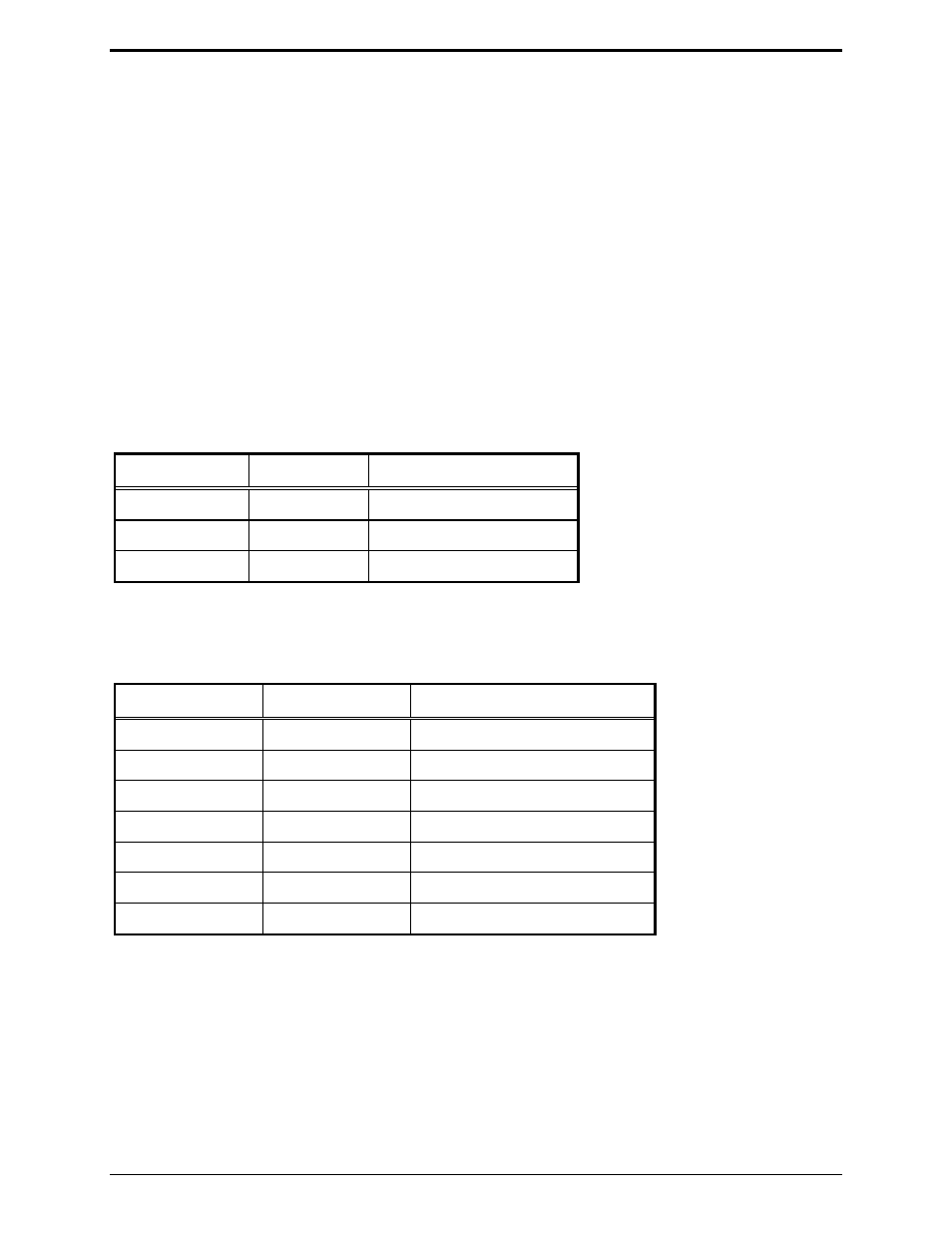
Pin 601 Pin # Color
Function
B
Red
TX PL disable return
B
Green/black
RX detector return
B
Blue/black
TX audio return
Twist the above listed leads together and solder to a short wire lead. Then strip a small section on the
black power lead close to the connector. Neatly solder the short lead from the returns to the stripped
section of the black power lead.
Pin 601 Pin #
Color
Function
5
Blue/white
TX audio (mic high)
6
Green/white
RX detector audio
3
Red/black
TX PL disable
4
Black
RX PL detect
8 White
PTT
1
Orange
Reverse burst inhibit
2
Orange/black
Reverse burst inhibit return
N
OTE
: The orange and orange/black leads (reverse burst inhibit and return) need to be connected only in
the signal search mode.
If the PL1877A is to be dc-powered, connect the red lead in the dc power cable to P601 pin 4, and the
black lead to P601 pin 6. Connect the other end of the dc power cable into the 5-pin DIN connector (DC
PWR) on the rear panel of the PL1877A. If the optional ac transformer and cable are to be used, install
the ac power connector into the 5-pin DIN connector (DC PWR) on the rear panel of the PL1877A.