Mitrek consolette – enhanced vox simplex mode – GAI-Tronics MRTI 2000 (No. PL1877A) Microprocessor Radio Telephone Interconnect Installation & Service Manual User Manual
Page 146
Pl1877A – Radio Installation
PL1877A Microprocessor Radio Telephone Interconnect
12/10 140
Mitrek Consolette – Enhanced VOX Simplex Mode
Make the following modifications and additions to the base station using spare screw terminals on TB1
and TB2.
1. RX Detected Audio - Run a wire to DETECTED AUDIO available at solder strip TB4-6 (local
control station only), or TB10-6 (remote control station).
2. PL Detect - Run a wire to SQUELCH DISABLE on the MITREK transmitter-receiver board. Set up
the PL detect circuit output for “or squelch” operation. (JU1 in, JU2 out on the PL deck for tone PL;
JU5 in, JU4 out for digital PL). If the radio has a busy light kit, refer to the schematic for jumper
information. If the busy light kit is not present, add a 5.6k, ¼ W resistor from SQUELCH DISABLE
to ground.
3. PL Stripping - Run a wire to the CD (code disable) stake pin on the PL deck.
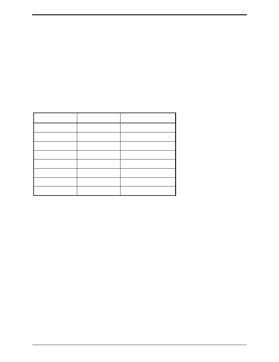
Now connect the PL1877A P1 interconnect cable to TB1 and TB2 as follows:
P1 Cable Color To
Function
Red/black Designated
spare
TX PL stripping
Red TB2-4 Ground
Green/black TB2-4
Ground
Green/white
Designated spare
RX detected audio
White TB2-5 PTT
Black
Designated spare
PL detect
Blue/black TB2-6
Mic
low
Blue/white TB2-7
Mic
high
Earth Ground – Run the supplied #12 or larger wire from the GND terminal on the rear of the PL1877A
to the base station chassis ground. This wire must be as short as practical, not coiled, and fastened
securely to the base station chassis. After this connection has been made, the installation is complete.
If the PL1877A is to be dc powered, connect the red lead in the dc power cable to TB2-1 and the black
lead to TB2-4; connect the other end of the dc power cable into the 5-pin DIN connector (DC PWR), on
the rear panel of the PL1877A.
If the optional ac transformer and cable are to be used, install the ac power connector into the 5-pin DIN
connector (DC PWR), on the rear panel of the PL1877A. If this is a control station in a repeater system
that transmits PL/DPL during transmit turn off delay, it is necessary that the repeater be set for zero turn-
off delay. (See Note 1).