Micor rcb repeater – GAI-Tronics MRTI 2000 (No. PL1877A) Microprocessor Radio Telephone Interconnect Installation & Service Manual User Manual
Page 155
PL1877A Microprocessor Radio Telephone Interconnect
PL1877A – Radio Installation
149
12/10
MICOR RCB Repeater
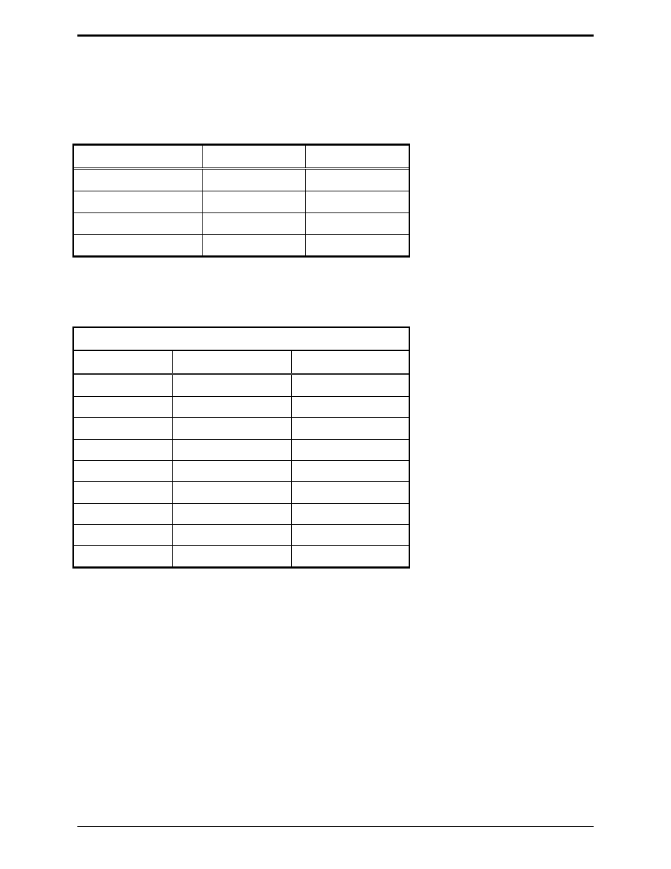
PL1877A Half-duplex mode: To facilitate easier installation and servicing, the screw terminals (TB3)
should be used for connection of the PL1877A P1 interface cable. The following jumper wires should be
soldered into the holes adjacent to the screw terminals rather than wrapping the jumper ends around the
terminals. Install the following jumpers:
From To
Function
1. Screw terminal #9
J5 pin 9
PL stripping
2. Screw terminal #13
Sta cont Pin 21
R1 disc
3. Screw terminal #15
F1-PL pin 22
Exciter input
4. Screw terminal #17
J2-10
PL indicator
In order to use the PL stripping function, a jumper must also be installed from P701 on the PL encoder
board to P964 on the transmitter interconnect board. This jumper is also used with the paging PL defeat
option.
Installation of P1 Interface Cable
Cable Color
To
Function
Red
Screw terminal #1
PL stripping return
Orange/black
Screw terminal #1
PTT return
Green/black
Screw terminal #1
RX audio return
Blue/black
Screw terminal #1
TX audio return
Red/black Screw
terminal #9
PL stripping
Green/white
Screw terminal #13
RX disc audio
White
Screw terminal #14
Repeater PTT
Blue/white
Screw terminal #15
TX audio
Black Screw
terminal #17
PL indicator
If the PL1877A is to be dc-powered, connect the red lead in the dc power cable to screw terminal #10
and the black lead to screw terminal #1; connect the other end of the dc power cable into the 5-pin DIN
connector (DC PWR), on the rear panel of the PL1877A. If the optional ac transformer and cable are to
be used, install the ac power connector into the 5-pin DIN connector (DC PWR), on the rear panel of the
PL1877A.
Earth ground - run the supplied #12 (or larger) wire from the GND terminal on the PL1877A to the base
station chassis ground. This wire must be as short as practical, not coiled, and fastened securely to the
base station chassis.