GAI-Tronics MRTI 2000 (No. PL1877A) Microprocessor Radio Telephone Interconnect Installation & Service Manual User Manual
Page 144
Pl1877A – Radio Installation
PL1877A Microprocessor Radio Telephone Interconnect
12/10 138
If the PL1877A is to be dc-powered, connect the red lead in the dc power cable to TB2-1 and the black
lead to TB2-4; connect the other end of the dc power cable into the 5-pin DIN connector (DC PWR), on
the rear panel of the PL1877A. If the optional ac transformer and cable are to be used, install the ac
power connector into the 5-pin DIN connector (DC PWR), on the rear panel of the PL1877A.
Earth Ground – Run the supplied #12 or larger wire from the GND terminal on the rear of the PL1877A
to the base station chassis ground. This wire must be as short as practical, not coiled, and fastened
securely to the base station chassis. After this connection has been made, the installation is complete.
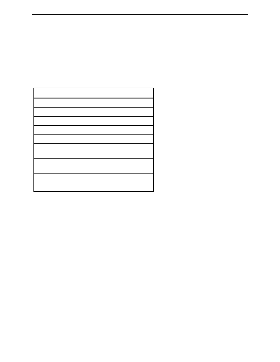
Using the Parameters Modification Procedure in this manual, set the following required parameter
settings:
Parameter Setting
1 0
(de-emphasis)
2
1, JU202 OUT (mid-level source)
3
0 (internal carrier detect)
4 Don’t
care
5
0 (internal squelch for carrier detect)
6
0 (No PL detect input required)
1 (PL detect input required)
7
0 (PL detect input is active low)
1 (PL detect input is active high)
9 1
(simplex)
10
0 (active low PTT sense input
All other parameters are programmed as applicable to system requirements. Refer to “Level Setting” in
the “Parameters Modification Procedure” section of this manual.