Internal diagnostics, Test 1 – tx softpot adjustment, Test 2 – dtmf decode thresholds – GAI-Tronics MRTI 2000 (No. PL1877A) Microprocessor Radio Telephone Interconnect Installation & Service Manual User Manual
Page 19: Test 3 – mobile-to-phone audio path
PL1877A Microprocessor Radio Telephone Interconnect
Installation
13
12/10
Internal Diagnostics
Test 1 – TX Softpot Adjustment
This test activates both the PTT and the PL strip output, accesses the phone line and generates 1000 Hz
to the phone line and transmitter. The
UP
or
DOWN
buttons are used to adjust the TX softpot,
UP
increases the TX level and
DOWN
decreases the level. As the
UP
or
DOWN
button is pressed the value
stored in gain stage U18 is displayed via the LEDs in binary form. When the
PATCH
ON/OFF
button is
pressed to exit Test 1, the TX softpot is set at the indicated TX level number. The TX softpot remains at
this value permanently unless it is again changed through Test 1.
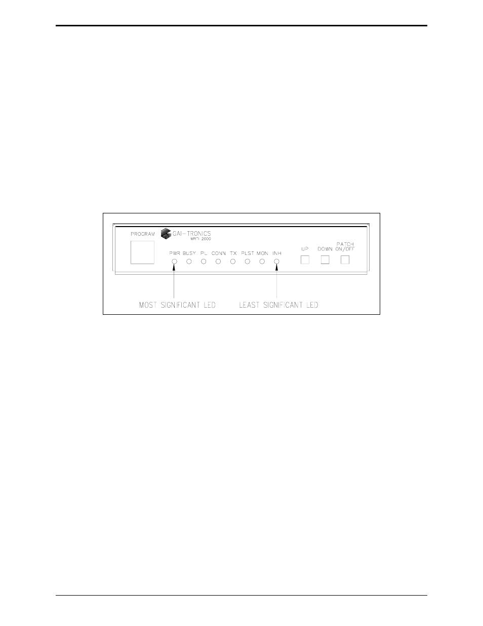
Test 2 – DTMF Decode Thresholds
Test 2 accesses the phone line and generates each of the 16 DTMF digits. The tones are generated at six
different levels. The PL1877A decodes its own DTMF, and the decoded digits are indicated on the five
least significant LEDs in binary form. Refer to the LED assignment diagram below. The most
significant LED indicates that the digit being generated has been decoded.
Digit cycling may be slowed down by pressing the
DOWN
button once or frozen by pressing the
DOWN
button a second time. Pressing the
UP
button speeds up the cycling process.
N
OTE
: A DTMF “0” is displayed as hexadecimal 10 (decimal 16) in binary.
Test 3 – Mobile-to-Phone Audio Path
This test accesses the phone line and routes mobile audio to the phone lines with autoleveling. Decoded
DTMF from the mobile is displayed via the 5 least significant LEDs in binary format. 15 dB of RX
audio attenuation may be toggled
ON
or
OFF
by pressing the
UP
button. When test 3 is entered, the
attenuator is in the state required by parameter 2.
Pressing the DOWN button toggles the state of the RX audio 6 dB per octave de-emphasis. When Test 3
is entered, the de-emphasis is in the state required by parameter 1. The three most significant LEDs
(refer to the LED assignment diagram above) are used to indicate the state of the following:
• Carrier Detect Input - LED 1 (bit 7)
• RX VOX - LED 2 (bit 6)
• Internal Squelch Detection - LED 3 (bit 5)
If the LED is lit, the input is active, if the LED is not lit the input is inactive.