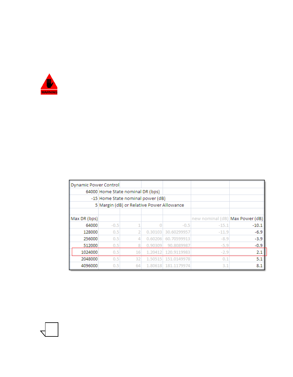
Figure c-2 excessive max power example – Comtech EF Data CDD-56X Series Vipersat User Manual
Page 142

Description
MN/22137, rev 1
C-6
Vipersat CDD-56X Series User Guide
The Max Power calculator takes into consideration all the above variables and
compares them to the modem BER waterfall curves to determine if the modula-
tor range is sufficient to achieve the budgetary information. If the calculator
returns an error [INVALID], the base level is either too high or the set parame-
ters have exceeded the capacity of the equipment.
Warning: The DPC maximum power setting is NO substitute for not
configuring the site maximum transmission parameters—bit rate,
modulation and power—in the VMS to match budgeted numbers.
During dynamic switching commands, the VMS could override DPC
limitations, if allowed. All commissioning settings for the site should
be matched in the VMS to prevent over-ranging of the DPC
maximum set points. See the VMS User Guide for site limit settings.
Many variables come into play when calibrating the base value, modem output
range, entrance link cable runs (length vs. attenuation), high power amplifier
conversion gains, and link budget calculations. Example: if the base data rate
value is 64 kbps calibrated to -15 dBm, and the site budget number was
1024 kbps, the resulting modulator Max Power value would surpass the hard-
ware limit (0 dBm, L-band), diminishing the margin efficiency by 2 dB, as
shown in figure C-2.
Figure C-2 Excessive Max Power Example
If the gain in the HPA is increased or the cable length/attenuation is reduced, the
modulator output could be decreased by 3 dB or more and the site could achieve
the max rate with a 1 dB site margin to spare.
Note: When configuring the site for Max Data Rate, the system operator must
test (commission) the antenna at the max rate to ensure that the relative
leveling of the uplink power does not exceed the 1 dB gain compression
NOTE
