Comtech EF Data CPA User Manual
Page 37
CPA C-Band Indoor Solid State Power Amplifier
Revision 1
Connectors and Pinouts
MN/CPA-IN.IOM
3–3
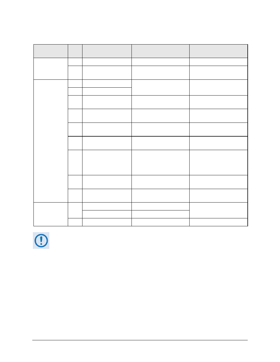
Table 3-1. CPA ISSPA Interface Connectors Summary
Connector
Group
Ref
Des Name
Connector Type
Function
RF
Sect. 3.2
J1 Tx IN
Type ‘N’ Female
RF Input
J2 RF OUT
CPR137G Waveguide
Flange
RF Output
Utility
Sect. 3.3
N/A SAMPLE | INPUT
Type ‘N’ Female
Front Panel –20 dBc and
–40 dBc test sample ports
N/A SAMPLE | OUTPUT
J4* REDUNDANT LOOP
Type 14-19 (19-pin) Circular
Conn Receptacle
Unit-to-Unit Redundant
Connection
J5 DISCRETE CONTROL Type 14-19 (19-pin) Circular
Conn Receptacle
User ISSPA M&C
J6 COM1
9-pin Type ‘D’ male
Serial Remote Comms
Interface (EIA-485)
J7* RF SWITCH
Type 12-10 (10-pin) Circular
Conn Receptacle
Waveguide Switch Interface
J8 10/100 ETHERNET
RJ-45 female
CAT5 10/100 BaseT
Ethernet – Remote Product
Management and Data
Traffic
J9A EXT REF IN
BNC Female
Optional External Reference
Input
J9B EXT REF OUT
BNC Female
Optional External Reference
Output
Power/Ground
Sect 3.4
J3
AC IN
See Sect. 3.4.1
Chassis prime power input
DC IN
Sect Sect. 3.4.2
N/A (Ground)
#10-32 stud
Common chassis ground
* These connectors are used in redundant operations only. See Appendix B. ISSPA
REDUNDANT OPERATIONS for further information about use of the ISSPA in 1:1 or 1:2
redundant systems.