B.2.2 redundancy kit control cabling – Comtech EF Data CPA User Manual
Page 129
CPA C-Band Indoor Solid State Power Amplifier
Revision 1
Appendix B
MN/CPA-IN.IOM
B–7
B.2.2
Redundancy Kit Control Cabling
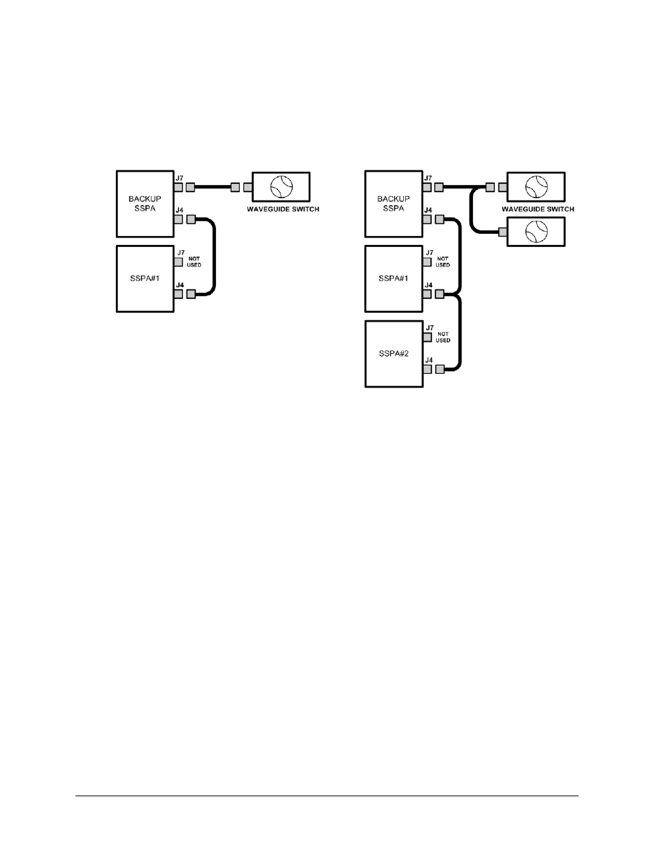
For either a 1:1 or a 1:2 redundant system, two control cable assemblies are required for setup as
shown in the Figure B-5 cabling schematics. Other RF coaxial cables and waveguides are required as
listed in Table B-1 and shown in Figure B-3.
Figure B-5. ISSPA Redundancy System – Control Cabling Schematics
The redundant loop cable, used for interconnection of the ISSPAs via their ‘J4 | REDUNDANT
LOOP’ connectors, has the following characteristics:
•
The cable assembly is not a “straight through” cable.
•
The cable assembly is labeled “BACKUP” on one end, and “SSPA#1” on the other end.
•
The cable assembly is wired so that, when connected to two ISSPAs, one ISSPA will
automatically configure itself as the Backup Controller and the other ISSPA will automatically
configure itself as the ‘PRIMARY SSPA’.
•
The ‘BACKUP SSPA’ communicates to the ‘PRIMARY SSPA’ via a serial interface that is also
provided by this cable assembly. The Backup SSPA uses this interface to acquire
configuration information from SSPA #1. This interface additionally provides the link for
virtual addressing as described in this manual in Chapter 7. SERIAL-BASED REMOTE
PRODUCT MANAGEMENT.
•
Summary fault relay contacts, which are used by the Backup SSPA as an input to its
switching logic, are also included in this cable assembly.
1:1 System Control Cabling
1:2 System Control Cabling