7 remote programming, 1 data of the serial interface, Remote programming – Avery Dennison ALX 720 User Manual
Page 81: Data of the serial interface, Alx 720
Operators Manual
ALX 720
4/09
Page 81
Remote programming
7. Remote programming
The machine has a serial interface according to the standard RS232C. Via this interface
parameters can be adjusted. All received commands are tested for syntax and legal value
range.
Invalid commands and parameters are ignored. An error message is not given in this case.
All commands received over the serial interface are tested for syntax and range; invalid
commands and out of range parameter values are ignored. A warning message is not given in
these cases. However in the case of framing, parity or overrun errors the warning "W__3" is
generated.
The commands are made up of sequences of ASCII characters. Each command starts with "#"
and "!" followed by a 4 character code. The reception of the "#" character indicates the start of
a new command to the machine.
The codes are similar to the parameter names shown in the display.
7.1 Data of the serial interface
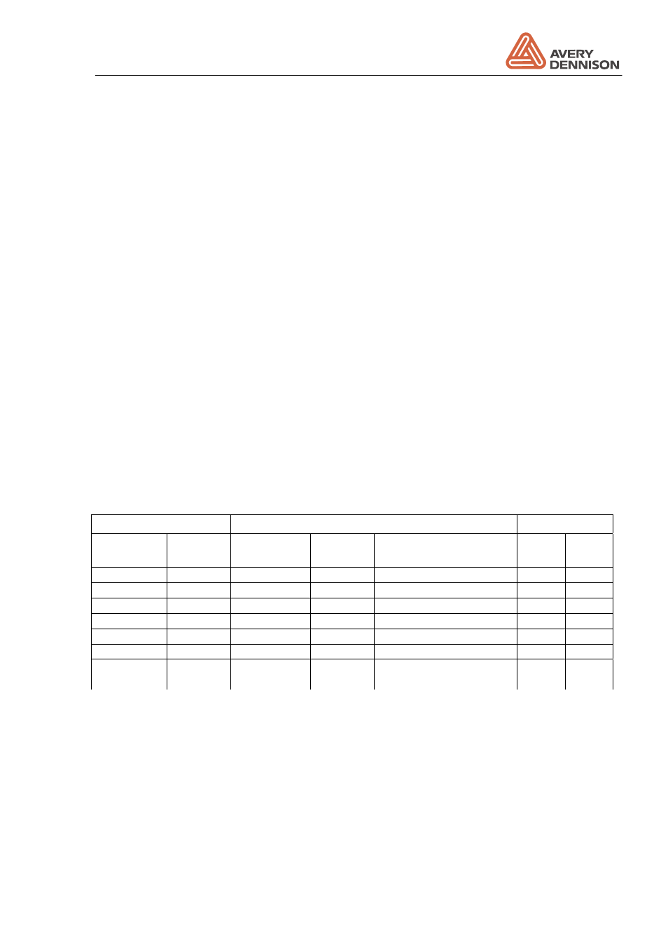
The pin connection of the interface plug is shown in the table below.
Dispenser connector
Signal description
PC
25 pol D-
Sub
9 pol D-
Sub
Direction
Code
Description
25 pol 9 pol
Socket 2
3
Output
TxD
Transmit data
3
2
Socket 3
2
Input
RxD
Receive data
2
3
Socket 5
8
Input
CTS
Clear to send
4
7
Socket 4
7
Output
RTS
Request to send
5
8
Socket 7
5
GND
7
5
Socket 20
4
Output
DTR
6
6
Socket 24
(if jumper
on)
+ 10V
For external use
8
All other pins are not connected.
Adjustable data values
Baudrate
150, 300, 600, 1200, 2400, 4800, 9600, 19200 Baud
Data bits
7 or 8 bits
Stop bits
1 or 2 bits
Parity
No Parity, Parity bit always 0, odd or even parity
Handshake RTS/CTS