1 installation – AMETEK SLM Series RevC User Manual
Page 24
Installation
Sorensen SLM-Series DC Load
2-2
M540071-01 Rev C
2.1
Installation and Removal of SLM-Series DC Plug in
Module
CAUTION:
Only qualified personnel should do installation and removal
.
Unless the SLM mainframe and the SLM-series DC electronic load module were purchased separately,
the load module should be installed in the mainframe before shipment from Xantrex.
Installation and removal procedures for the SLM-series load module are listed below.
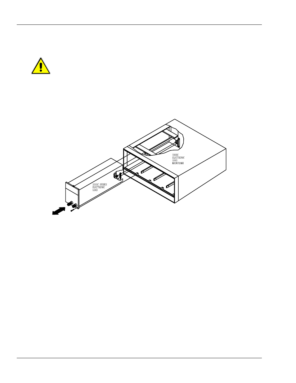
Figure 2-2 Plug-in Installation and Removal
2.1.1 Installation
1 Turn the SLM mainframe power OFF before inserting any load module, or damage may
occur to the plug-in module circuitry.
2. Align the upper and lower grooves of the mainframe with the upper and lower guides of the
selected compartment.
3. Push the module in and press firmly on the binding posts (labeled, “DC Input” in Figure 2-1)
of the front panel to seat the circuit board into the interconnecting jack.
4. Using a screwdriver, tighten the screw on the lower right corner of the SLM-series load
module front panel. The screw location is shown in Figure 2-1.
5. DO NOT turn the mainframe power ON until after all of the electronic modules are completely
installed.