D*ap8 – Junger Audio D*AP8 Digital Audio Processor User Manual
Page 8
D*AP8
6
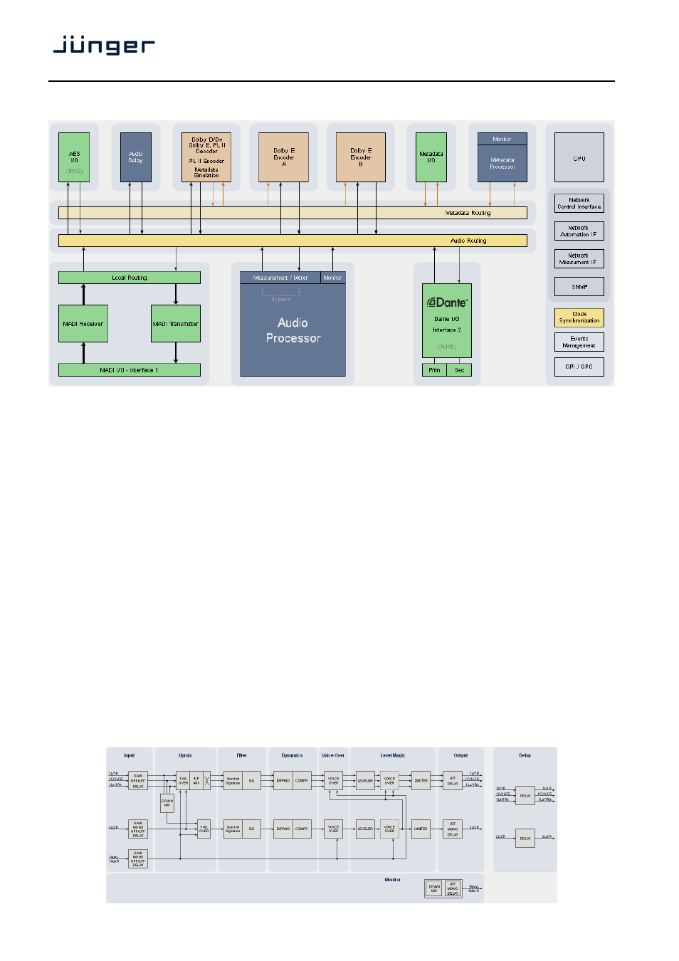
Device block diagram:
The above schematic shows the principal blocks of a fully loaded D*AP8.
The core of the is the audio processor with 10 inputs, 8 outputs and a 2ch monitor output.
Dolby Decoding/Emulation is based on a hardware decoder option.
It also provides a Dolby E encoder that can be licensed
An optoional Dolby encoder may be fitted to provide an encoded output either in Dolby E (D-E) or one of the
consumer formats Dolby Digitial (D-D) AKA AC3, Dolby Digital plus (D-D+) or AAC and its derivates.
This will save rack space and installation cost and offers a fully integrated solution.
Four AES I/Os on the motherboard are provided for digital line operation. The respective connectors have
relay bypass for power fail operation. The bypass ciruit may be disabled by internal jumpers.
Two interface slots are provided to carry optional 3G / HD / SD-SDI, MADI, Dante, AES I/O or even analog
expansion modules. It allows for extremely flexible interfacing of the D*AP8 in TV installations.
For comprehensive metadata processing the has 9-pin serial metadata I/O connectors. All metadata
functions are centralized in a metadata generator. Furthermore you will have the possibility to emulate the
influence of Dolby metadata on the audio signals for stereo or surround configurations and surround
down mixes, without the need to involve an encoder and a decoder.
The sync circuit can deal with all practical formats to integrate the D*AP8 into digital facilities. Other devices
may be synchronized by the word clock output of the D*AP8 unit. The frame reference for D-E encoding,
can be shifted to align the D-E guard band.
The D*AP8 has 8 balanced GPIs and 8 SSR closure GPOs. This enables the user to simply recall presets or
call events, change device configurations and report general status information.
Audio processing blocks: