D*ap8 – Junger Audio D*AP8 Digital Audio Processor User Manual
Page 62
D*AP8
60
setup GUI – AUDIO PROCESSOR – Fail Over (4 x 2 program configuration)
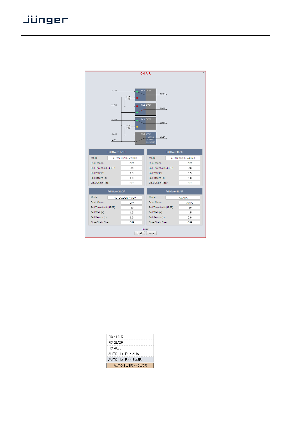
For the 4x2 Program Configuration (SYSTEM > Setup > Program Configuration) the D*AP8 offers
four independent Fail Over circuits (see Overview sketch).
The source for the Fail Over circuit can be either the adjacent program input (e.g. input 2L/R for the
program input 1L/1R) or the AUX input. The Mode switch will select the respective signal path.
See the example above for the four program outputs :
program 1 (1L/1R)
has a valid input signal and is prepared for auto switch over
to the second program input 2L/2R.
program 2 (2L/2R)
has no valid input and has automatically switched over
to the AUX input.
program 3 (3L/3R)
has a valid input and is prepared for auto switch over
to input 4L/4R, input 4L/4R has valid input.
This is indicated by the yellow soft LED.
program 4 (4L/4R)
is fix connected to AUX. Signal input is mono L.
Fail Over 1L/1R
Example description of the fail over function blocks
MODE
The Fail Over output can be permanently
connected to:
* its program input 1L/1R
* its adjacent program input 2L/2R
* or to the AUX input.
Automatic switch over in case of an input
failure may be configured for the AUX or the
adjacent 2L/2R input.