Coefficient reloading timing diagrams, Coefficient reloading timing diagrams –22 – Altera FIR Compiler User Manual
Page 64
4–22
Chapter 4: Functional Description
Timing Diagrams
© May 2011
Altera Corporation
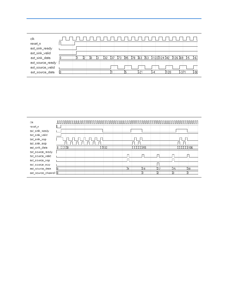
If the filter is time-shared by N, (that is the Clocks to compute value is N), then new
input data is required every N clock cycles and new output data is produced every
N×M cycles.
shows the timing diagram for a Multibit serial filter with two serial units
and an input data width of 8-bits.
The filter needs new data every four clock cycles and produces an output every 8
clock cycles. Because the flow is controlled by
ast_sink_ready
, the input data
fetching occurs in a groups, where
ast_sink_ready
goes high for five cycles and
five new data inputs are taken at once. Then
ast_sink_ready
goes low and no data
is accepted for 15 cycles. The
ast_source_sop
and
ast_source_eop
signals mark
the start of packet and end of packet respectively.
Coefficient Reloading Timing Diagrams
The coefficient reload ports are not Avalon-ST compliant and work independently of
the enable and reset signals, and of the Avalon-ST controller. You can load new
coefficients even if the filter is under reset conditions or not enabled.
Serial, multibit serial, and parallel FIR filters use a distributed arithmetic algorithm
and the coefficients stored in memory blocks are precalculated. When updating the
coefficients, the new coefficients first go through a pre-calculating algorithm. The first
data to reload in each memory block is always zero. The rising edge of the coef_we
signal resets the internal data address counter for reloading.
Figure 4–22. Single Channel, Decimation-by-2 (Parallel, MCV Single Cycle)
Figure 4–23. Three Channel, Decimation Filter (Serial, MBS, MCV Multicycle)