Altera FIR Compiler User Manual
Page 61
Chapter 4: Functional Description
4–19
Timing Diagrams
© May 2011
Altera Corporation
This filter accepts an input every clock cycle and produces an output every clock
cycle. Because
ast_source_ready
and
ast_sink_valid
are kept at high, the
filter can internally run fully streaming. An input is transferred when
ast_sink_ready
and
ast_sink_valid
are both high during the rising edge of the
clock.
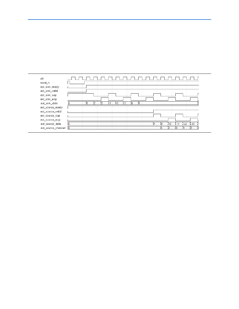
shows a three channel filter with the same specification as the single
channel filter in
.
The FIR filter now has start of packet (
sop
) and end of packet (
eop
) signals for both
the sink (input) and source (output) modules. The first input data to the FIR filter is
accompanied by the high value of the
ast_sink_sop
port, which means it belongs
to the first channel.
The third input data is marked as an end of packet by the high value of the
ast_sink_eop
port. This sequence repeats itself continuously at each cycle.
When the filter output is ready,
ast_source_valid
goes high, and for the first data
output
ast_source_sop
goes high to mark the start of the packet. The
ast_source_channel
output shows to which channel that particular output
belongs. The last channel data is marked with the high value of the
ast_source_eop
port.
demonstrate another single channel, single
rate filter timing diagram. In these diagrams, the FIR filter requires input data every
three clock cycles and produces one output data every three clock cycles. In general,
MCV multicycle filters (when the Clocks to Compute value is greater than one),
Multibit Serial filters, and Serial filters require a new input data every N clock cycles
where N represents the following:
■
For an MCV multicycle filter, N is the clocks to compute value
■
For a Multibit Serial filter, N = (input data bit width)/(number of serial units)
■
For a Serial filter, N = (input data bit width +1)
Figure 4–16. Three Channel, Single Rate (Parallel or MCV Single Cycle)