Reset and global clock enable operations, Single rate filter timing diagram – Altera FIR Compiler User Manual
Page 60
4–18
Chapter 4: Functional Description
Timing Diagrams
© May 2011
Altera Corporation
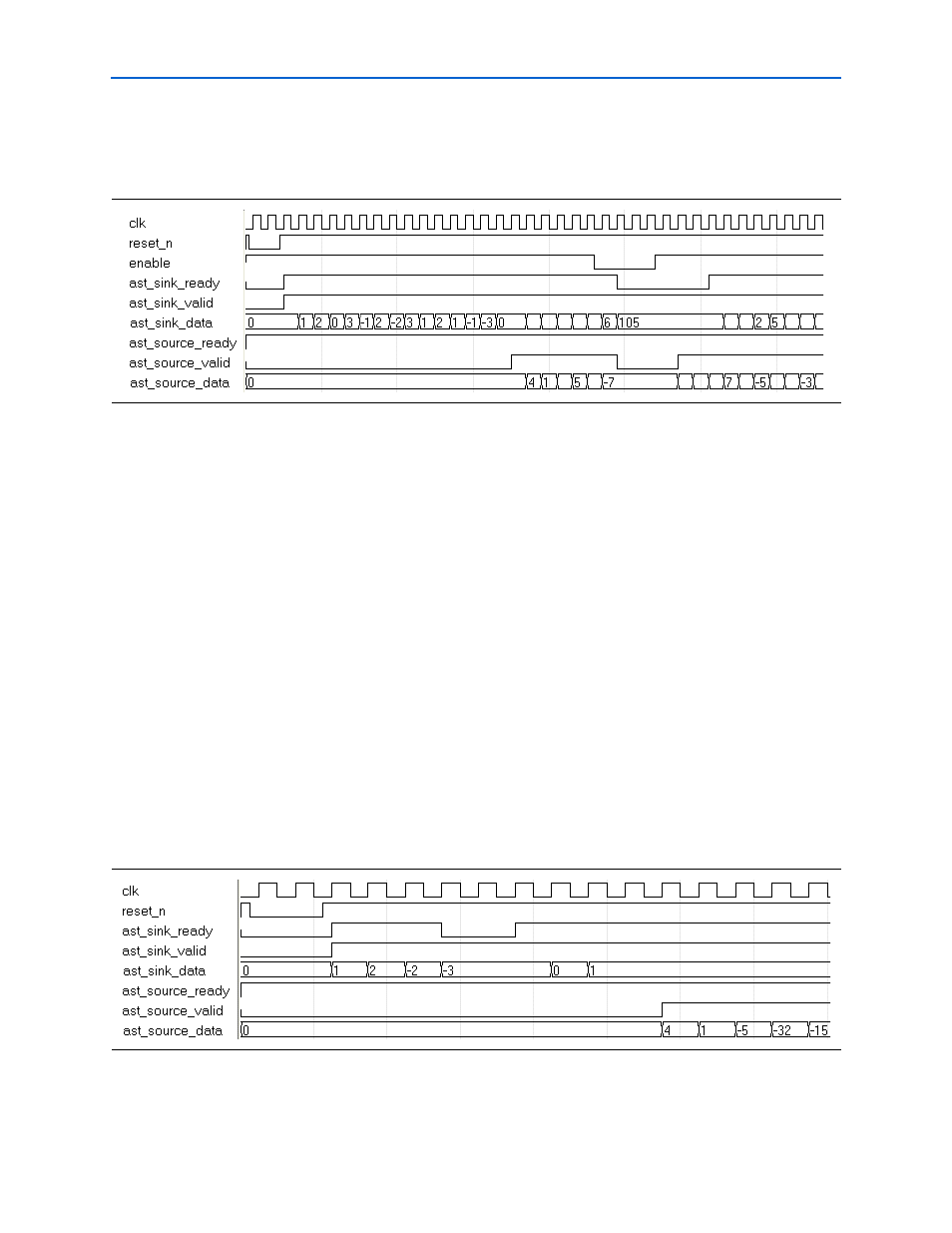
Reset and Global Clock Enable Operations
shows the reset and clock enable operations.
When the reset (
reset_n
) is applied to the filter, the
ast_sink_ready
and
ast_source_valid
signals go low. At the next rising edge of the clock (
clk
) after
the reset is released,
ast_sink_ready
goes high indicating that the design is ready
to accept new data. This behavior is independent of the filter type and architecture
because there is a small FIFO in the Avalon-ST controller.
The global clock enable signal (where it exists) can also control when the FIR
MegaCore function is stalled. The Avalon-ST controller operates independent of the
global clock enable. The FIR is stalled as soon as the global clock enable goes low.
However, because of the internal buffering in the Avalon-ST controller, the
ast_sink_ready
signal can go low in the following cycles. For the same reason,
when the global enable is high,
ast_sink_ready
may go high at a later cycle.
The
ast_source_valid
signal is produced by the Avalon-ST controller is therefore
independent of the global clock enable. When the available valid data is transferred,
and no more output data is available, it goes low until there is valid data to transfer.
Single Rate Filter Timing Diagram
shows the timing diagram of a single channel single rate FIR filter
implemented either in MCV architecture with a Clocks to Compute value of 1, or in
Parallel architecture.
Figure 4–14. Reset and Clock Enable Protocol
Figure 4–15. Single Channel, Single Rate (Parallel or MCV Single Cycle)