Decimation filter timing diagrams, Decimation filter timing diagrams –21, Show a single – Altera FIR Compiler User Manual
Page 63
Chapter 4: Functional Description
4–21
Timing Diagrams
© May 2011
Altera Corporation
These timing diagrams also apply to an MCV single cycle filter. An interpolation-by-2
filter produces two output data for each input data it receives. As seen from the
figures, a new output is produced every cycle. This means that new input data is
required every other cycle.
This behavior can be observed easily when the flow of data is controlled by the
ast_sink_valid
signal as in
shows the timing diagram for a three channel, interpolation-by-2 filter
with a Parallel or MCV single cycle architecture illustrating the additional start of
packet and end of packet signals.
The timing diagrams for Serial, Multibit serial, and MCV multicycle filters would be
similar to
and
. For an MCV filter with a Clocks to Compute
value of N, and interpolation factor M, new input data is required every N×M clock
cycles and a new output would be produced every M clock cycles.
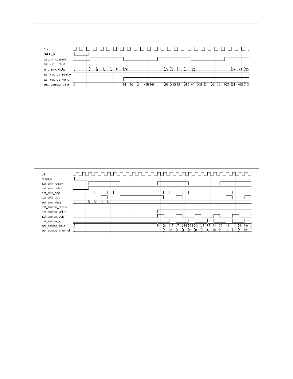
Decimation Filter Timing Diagrams
In a decimation-by-M filter, for every M input data, one output will be produced.
shows that for a Parallel or MCV (single cycle) decimation-
by-2 filter, new input data is taken each clock cycle and new output data is produced
every other clock cycle.
Figure 4–20. Single Channel, Interpolation-by-2 (Parallel, MCV Single Cycle), ast_sink_ready Control
Figure 4–21. Three Channel, Interpolation-by-2 (Parallel, MCV Single Cycle)