Echelon FTXL User Manual
Page 238
226
Example FTXL Applications
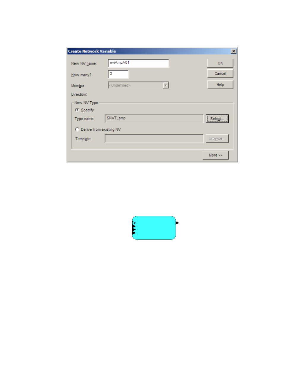
vi. The Create Network Variable dialog should look similar
Figure 27. The LonMaker Create Network Variable Dialog for nviAmpA01
vii. Click OK to close the Create Network Variable dialog.
c. Click OK to add the three input network variables (named
nviAmpA01, nviAmpA02, and nviAmpA03) to the virtual
functional block and close the Choose a Network Variable dialog.
After you add the four dynamic network variables to the virtual functional block,
it should look similar to Figure 28.
nciNvType
nvoAmpA
nviAmpA01
nviAmpA02
nviAmpA03
Virtual Functional Block
Figure 28. The Virtual Functional Block for the Dynamic Interface Example
To demonstrate that the four dynamic network variables act as a logical circuit,
open the LonMaker Browser for the FTXL device and set the values for the three
input network variables and observe the value of the output network variable,
which should be the sum of the three inputs:
1. Right-click the FTXL device on the LonMaker drawing and select Browse
to open the LonMaker Browser window.
2. Select the row for the nviAmpA01 network variable.
3. Enter a value for the network variable in the Value field at the top of the
window. Click the Set value button to set the network variable’s value.
4. Select the row for the nvoAmpA network variable, and click the Get value
button to see its current value.