5 ramping-down signals psd and msd, 6 in-position signal inp, Ramping-down signals psd and msd – ADLINK PCI-8134A User Manual
Page 34: In-position signal inp
24
• Signal Connections
3.5
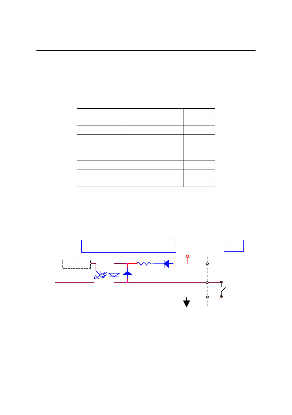
Ramping-down Signals PSD and MSD
There are two ramping-down
(Slow−Down) signals PSD and MSD for one
axis. The relative signal name, pin number and axis number are shown in
the following table.
CN2 Pin No
Signal Name
Axis
#
39
PSD1
40
MSD1
45
PSD2
46
MSD2
89
PSD3
90
MSD3
95
PSD4
96
MSD4
The signals connection and relative circuit diagram is shown in the following
diagram. Usually, limit switches are used to generate the slow
−down
signals to make motor operating in a slower speed. For more details of the
SD operation, please refer to section 4.3.1.
3.6
In-position Signal INP
The in-position signals INP from the servo motor driver indicate the
deviation error is zero, that is the servo position error is zero. The relative
signal name, pin number and axis number are shown in the following table.
EX+24V
I
f
=6mA Max.
Filter
Circuit
Motion ASIC
PSD
MSD
4.7K
EXGND
Inside PCI-8134/PCI-8134A
CN2
Switch