9 cn4 pin assignments: simultaneous start/stop, 10 jumper setting, Cn4 pin assignments: simultaneous start/stop – ADLINK PCI-8134A User Manual
Page 24: Jumper setting
14
• Installation
2.9
CN4 Pin Assignments: Simultaneous Start/Stop
The signals on CN3 is for simultaneously start/stop signals for multiple axes
and multiple cards.
No.
Name
Function(Axis )
1
GND Bus power ground
2
STP
Simultaneous stop signal input/output
3
STA
Simultaneous start signal input/output
4
STP
Simultaneous stop signal input/output
5
STA
Simultaneous start signal input/output
6
+5V
Bus power, +5V
Note: +5V and GND pins are directly given by the PCI Bus power.
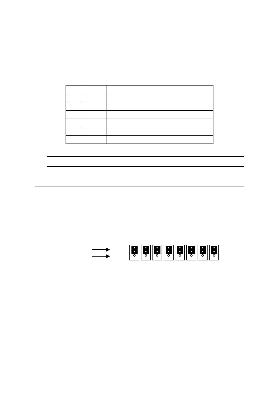
2.10
Jumper Setting
The J1~J8 is used to set the signal type of the pulse output signals (DIR
and OUT). The output signal type could be differential line driver output or
open collector output. Please refer to section 3.1 for details of the jumper
setting. The default setting is the differential line driver mode.
Line Driver
Open Collector
Figure 2.3 Illustration of PCI-8134 jumpers
1
2
3
J1 J2 J3 J4 J5 J6 J7 J8