12 termination, Figure 3-42: example of pattern match – ADLINK PCIe-7360 User Manual
Page 85
Operations
75
PCIe-7360
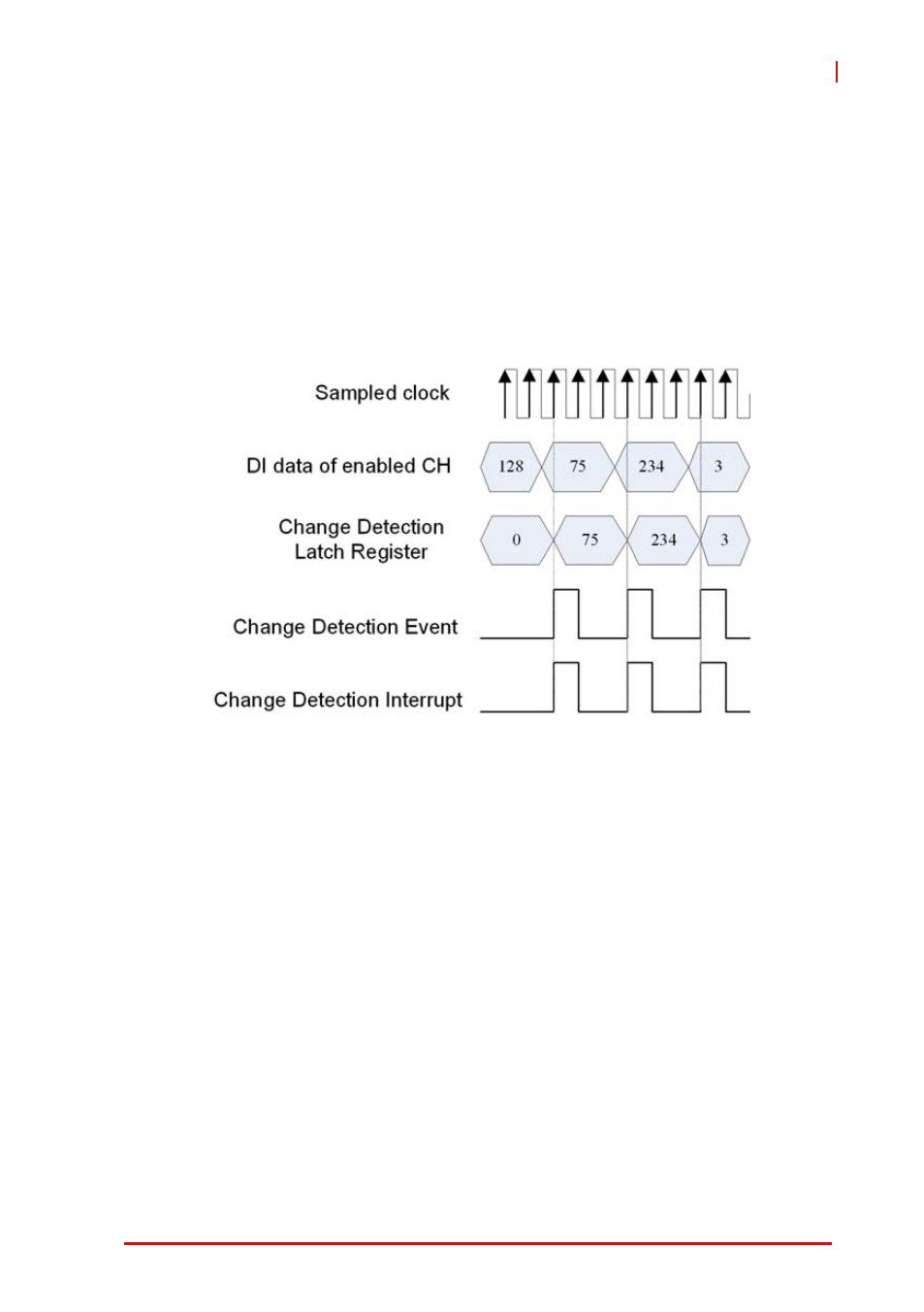
In COS mode, the DI data are sampled by 125 MHz clock rate.
Therefore, the pulse width of the DI data should be longer than
8ns. Otherwise, the change detection latch register won’t latch the
correct input data.
An example of 8 channel change detection operation is shown.
Any level change of the enabled DI data lines is detected and then
generate the event and interrupt. The corresponding DI data is
latched into change detection register.
Figure 3-42: Example of Pattern Match
3.12 Termination
Proper termination is very important for applications using
high-speed digital data transfer to eliminate the signal reflection
caused by cables, wiring, connectors, or PCB traces and improve
signal quality.
The output impedance (source impedance) of the PCIe-7360 is 50
Ω and the characteristic impedance of the SCSI-VHDCI cable is
also 50 Ω. When you connect to a DUT with 50 Ω input imped-
ance, the best impedance matching is achieved, but the voltage
level sensed by the DUT is half of the PCI-7360’s output voltage
due to voltage-divider principles. You can also connect to a DUT
with a high impedance (at least 1 - 100 kΩ) if precision timing and
excellent signal integrity is not so critical. The voltage level sensed