Do dma in burst handshake mode 2, Figure 3-21: do burst handshake timing diagram, Figure 3-22: do burst handshake 2 timing diagram – ADLINK PCIe-7360 User Manual
Page 63
Operations
53
PCIe-7360
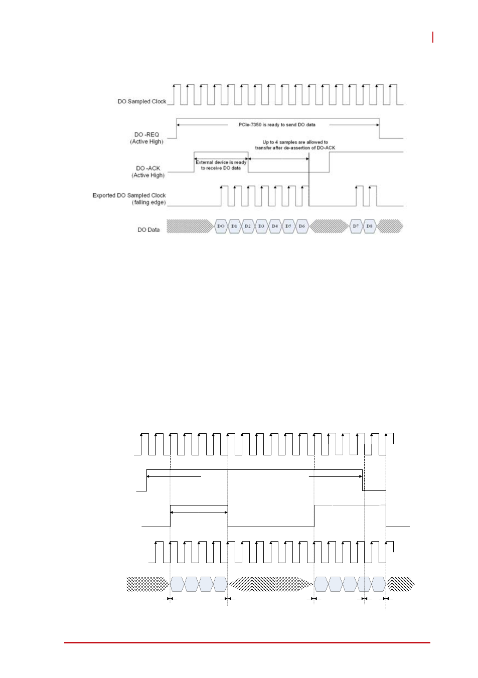
Timing of DO DMA in burst handshake mode is as shown.
Figure 3-21: DO Burst Handshake Timing Diagram
DO DMA in Burst Handshake Mode 2
DO burst handshake mode 2 improves tolerance in burst hand-
shaking applications with large wire delay. In this mode, the
PCIe-7360 confirms availability of the receiver indicated by the
DO-ACK signal before it starts to send data. Once the DO-ACK is
asserted, the external device (receiver) maintains assertion of the
DO-ACK signal before its input buffer becomes too small. When
the DO-ACK is de-asserted, indicating the receiver’s buffer is low
on space for new data, the PCIe-7360 is still allowed to send 4
data to the receiver, and the receiver has to receive the data. Tim-
ing of burst handshake mode 2 is as shown.
Figure 3-22: DO Burst Handshake 2 Timing Diagram
DO
DO Data
Exported DO Sample Clock
DO Sample Clock
DO -ACK
(Active High)
DO -REQ
(Active High)
D1
D2
D3
D4
D5
D7
PCIe-7360 DO FIFO is empty or paused
PCIe-7360 is ready to
send DO data
External device is ready to receive DO data
D6
D8
DO data transfer starts
(DI-REQ & DI-ACK are
all asserted)
Wait DO-REQ
asserted
Wire delay + DO
response time
DO data transfer stops
DI data transfer
restart
(DI-REQ & DI-ACK
are all asserted)
(DO-REQ is de-asserted)
DO stop