Di dma in handshake mode, Figure 3-13: do timing diagram, Define di-req and di-ack signal (afi0 to afi7) – ADLINK PCIe-7360 User Manual
Page 51
Operations
41
PCIe-7360
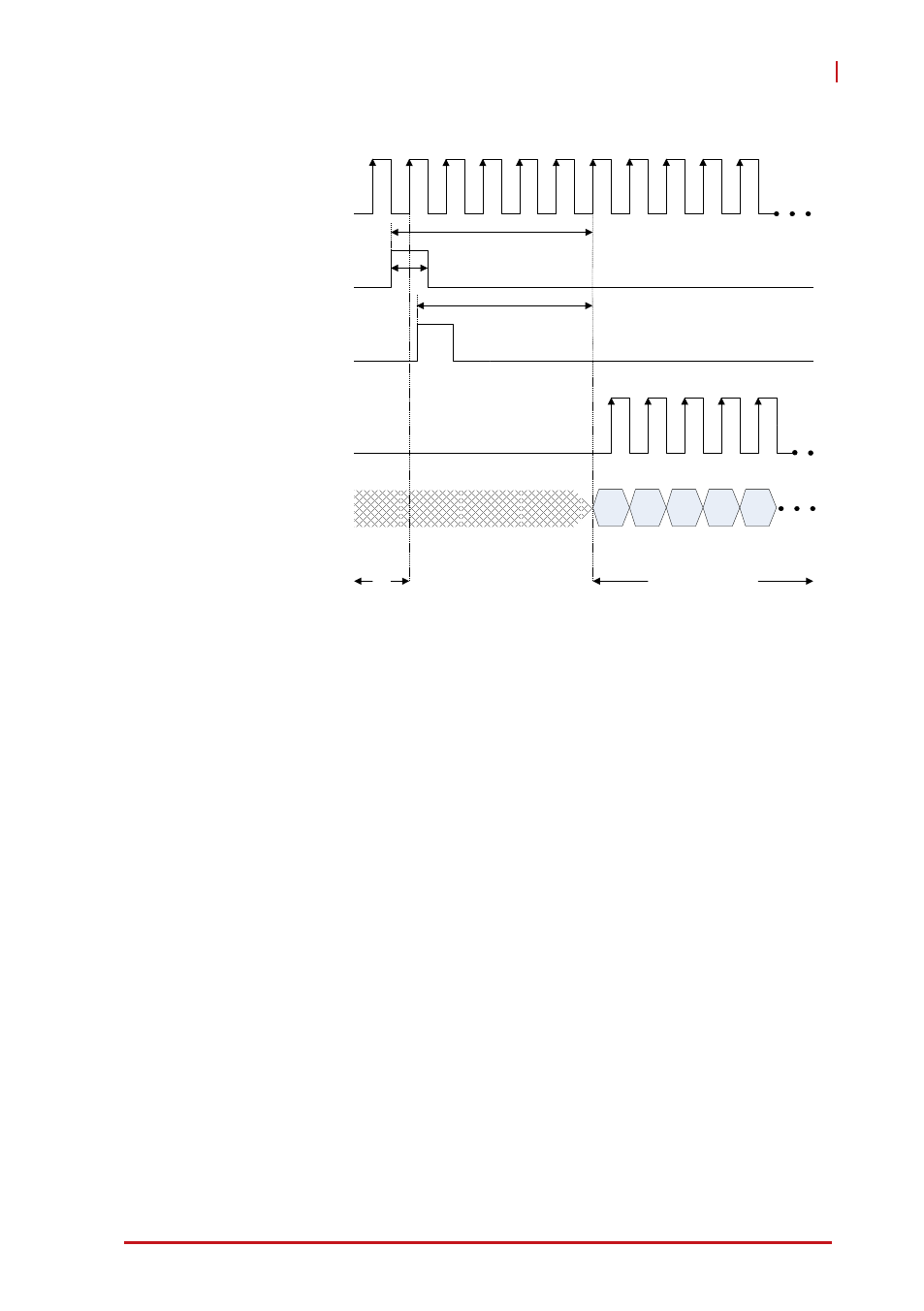
Figure 3-13: DO Timing Diagram
DI DMA in Handshake Mode
For the DI pattern acquisition operation in handshake mode,
PCIe-7360 card can acquire input data from external devices by
handshake data transfer through DI-REQ input signal and DI-ACK
output signal of AFI interface. The operation sequences are listed
as follows:
Step1: Configuration
X
Define DI port configuration (32/24/16/8-bits data width)
X
Define DI logic level configuration (3.3/2.5/1.8V)
X
Define DI-REQ and DI-ACK signal (AFI0 to AFI7)
Z
For example: if configure AFI3 as DI-REQ and AFI4 as
DI-ACK, and then you must connect the handshake sig-
D0
D1
D2
DO Sampled Clock
Start Trigger
(DO-Start)
DO Data
Write data to
external device
Wait for
start trigger
t
W
t
W
= Minimum detectable trigger width
D3
D4
t
ET2D
t
ET2D
= Delay from external trigger to do data out (about 5 cycle)
Exported DO Sampled Clock
(falling edge)
Software Trigger out
(DO-SW)
t
IT2D
t
IT2D
= Delay from software trigger out to do data out (about 4 cycle)