Preheat system – Generac Power Systems 53187 User Manual
Page 119
Attention! The text in this document has been recognized automatically. To view the original document, you can use the "Original mode".
PARTS
ENGINE ELECTRICAL SYSTEM
SECTION 5.4
PREHEAT SYSTEM
Section 5.4
PREHEAT SYSTEM
Introduction
The generator control panel m ounts a PREHEAT
sw itch. W ^hen actuated, this sw itch turns on a glow plug
in each engine cylinder. The glow plug acts as a heating
elem ent to w arm the engine com bustion cham bers and
provide quicker, easier starts in cold w eather.
To w arm the engine com bustion cham bers and
provide quicker cold w eather startup, push the panel
PREHEAT sw itch in and hold for about 15-30 seconds.
DO NOT EXCEED 30 SECONDS PREHEAT TIME.
NO TE: A PREHEAT sw itch Is also Included on the
optional
rem ote-m ounted
start/stop
panels.
See
Section 5.7 (Part 5, Section 5.7).
Units with Time 1 DC Control System
a ly
Units w ith a Type 1 DC control system are
equipped w ith a crank relay (CR1) and a run relay
(CR2). The crank relay (CR1) rem ains energized only
w hile the start/stop sw itch is held at its *Starf position
(engine cranking). On Type 1 units, the preheat func
tion occurs w hen CR1 is energized and its norm ally-
open contacts are closed.
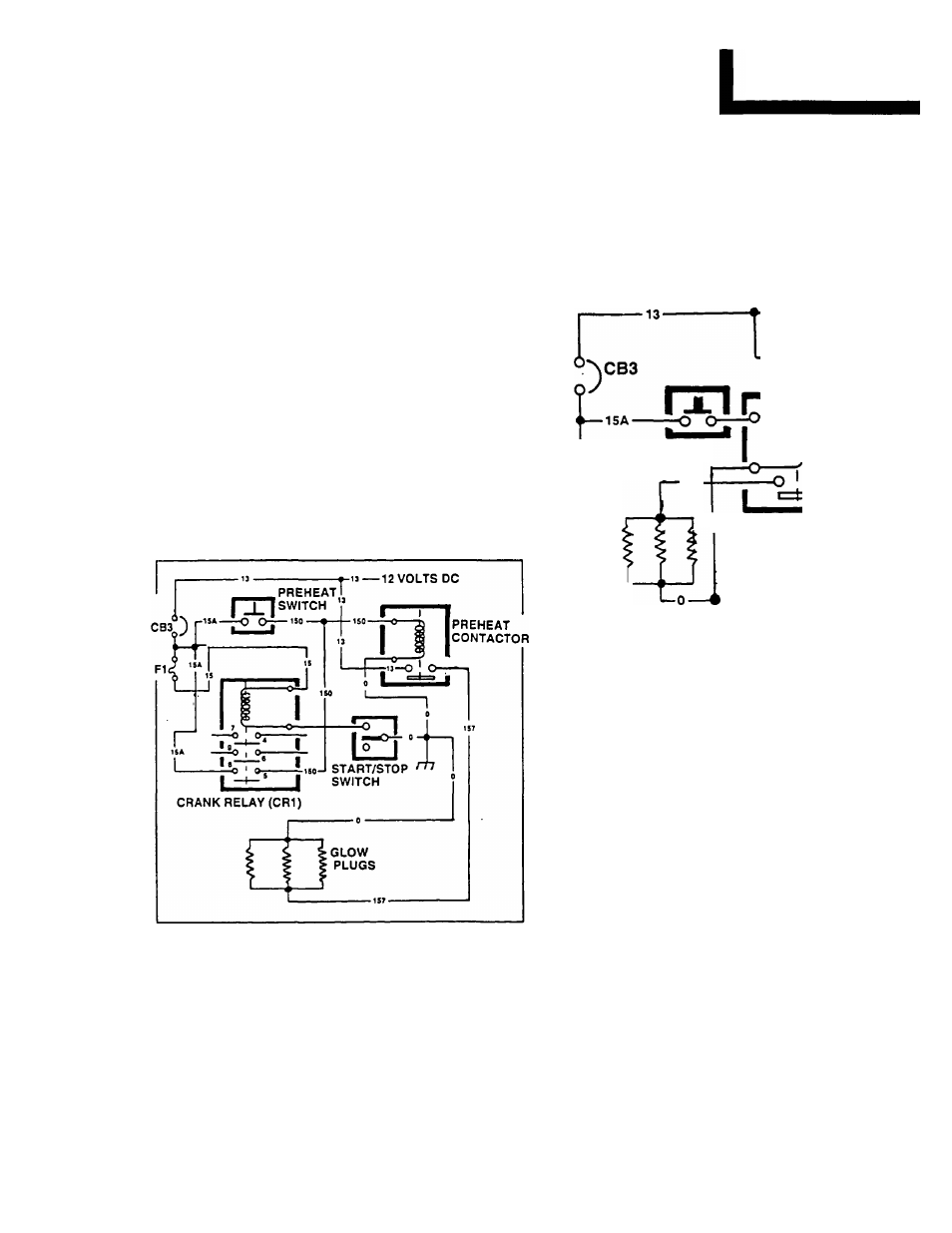
Figure 1. Preheat System - Type 1 DC Control
See Figure 1. Battery voltage Is available to the
preheat sw itch contacts. W hen the sw itch is closed,
battery voltage is delivered to the preheat contactor
coil. The coil energizes, the contacts close, and battery
voltage is delivered to the glow plugs.
During cranking (CR1 energized), 12 volts DC is
delivered across the closed CR1 contacts to the pre
heat contactor coil. Preheat occurs.
Units with Type 2 & 3 DC Control System
Rgure 2 is an operating diagram of a typical pre
heat circuit on units w ith Type 2 and 3 DC control
system . The preheat function w ill occur w hen the pre
heat contactor (PHC) is energized by actuating the
preheat sw itch to its closed position.
•13-12 VOLTS DC
13
PREHEAT
FI SWITCH
157
GLOWL
PLUGS
? PREHEAT
CONTACTOR
GROUND
Figure 2. Preheat System - Type 2 & 3 DC Control
Glow Plug Construction
See Figure 3. A thin, coiled HEAT W IRE is encased
in sintered m agnesium oxide pow der and enclosed by
a stainless steel SHEATH. One end of the w ire is
w elded to the SHEATH, the other end to the CENTER
ELECTRODE. W hen voltage is applied to the HEAT
W IRE, the w ire is heated.
1. Heat Wire
2. Sheath
3. Asbestos
4. Body
5. Nut
6. Magnesium Oxide Powder
7. Insulating Bushing
8. Center Electrode
(?)
(?)
T
©
Figure 3. Glow Plug Construction
PAGE 5.4-1