Battery charge system – Generac Power Systems 53187 User Manual
Page 117
Attention! The text in this document has been recognized automatically. To view the original document, you can use the "Original mode".
PARTS
ENGINE ELECTRICAL SYSTEM
1
SECTION 5.3
BATTERY CHARGE SYSTEM
Section 5.3
BATTERY CHARGE SYSTEM
Components
See Figure 1, below . An engine driven ALTERNA
TOR delivers an AC output to the DC VOLTAGE REG
ULATOR. The REGULATOR senses battery voltage at
its Term inal 5. The REGULATOR rectifies the ALTER
NATOR output and regulates the direct current flow to
the BATTERY.
The DC Alternator
A belt driven, perm anent m agnet type alternator Is
used. Alternator m aintenance Is lim ited to replacem ent
of parts. The alternator is show n In Rgure 3 on the next
page. The alternator produces alternating current
w hich is then rectified by the voltage regulator.
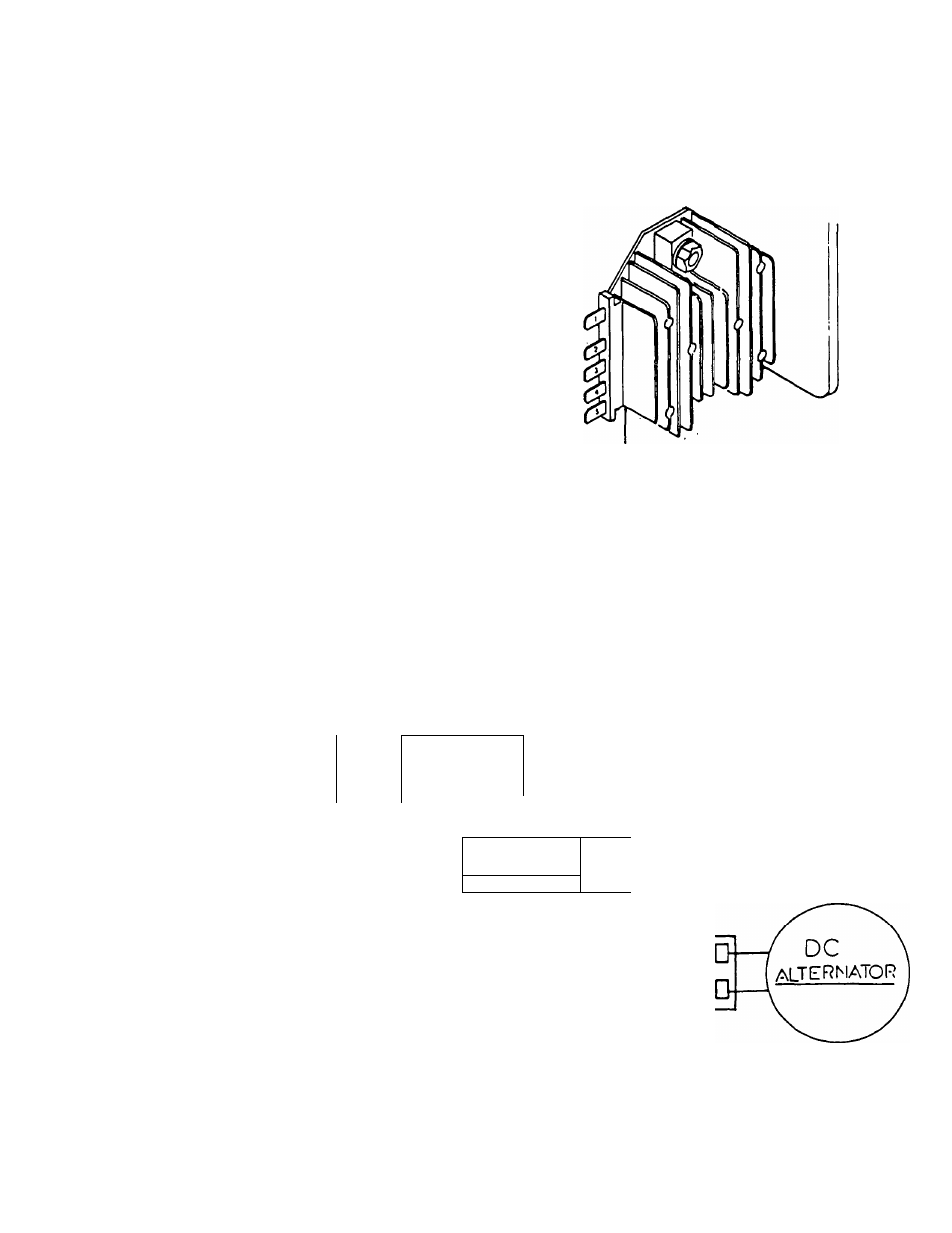
DC Voltage Regulator
The solid state voltage regulator (Figure 2) is
housed in an alum inum heat sink. Ail parts are covered
by an epoxy resin, m aking the unit non-repairable.
Regulator connector pins are num bered from left to
right as follow s:
□ Term inal 1: Charging output to battery (12.5-14.5
volts).
□ Term inal 2: W ire 48, AC input from alternator.
□ Term inal 3: W ire 49, AC input from alternator.
□ Term inal 4: Not used (charging indicator lam p con
nection.
□ Term inal 5: W ire 15, sensing input from battery.
Figure 2. DC Voltage Regulator
Í
o
o
¿
GROUND
r
STARTER 12 VOLTS
CONTACTOR BATTERY
+ 12 VOLTS
DC
voltage
bai
teiry
voltage
h
:
REGULATOR
12 3 4 5
15
T T T ~ T
FUSE
-13 A-
30 AMP
-48
-49
-□
Figure 1. Battery Charge System Diagram
PAGE 5.3-1