Top Flite TOPA0130 User Manual
Page 47
❏
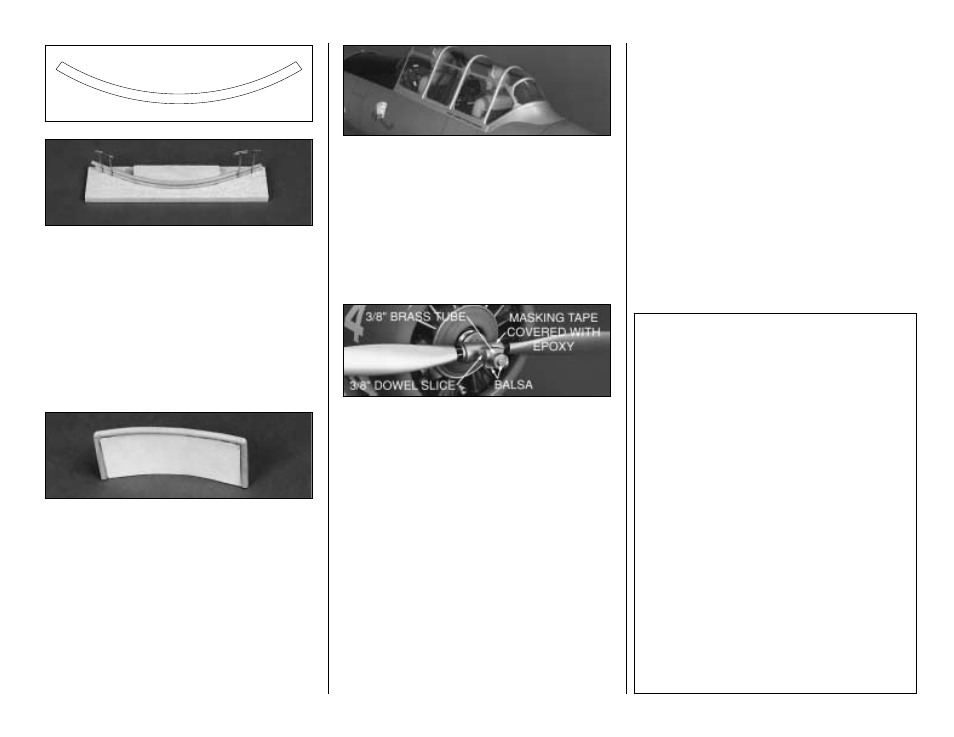
7. Seat backs can be made using 1/8" dowel
(not included) and card stock (file folder or index
card). Make a bending jig from scrap 1/4 balsa,
using the pattern shown above to set the radius.
Cut and bend two 1/8" x 3" lengths of the dowel
to form the top rail. Hint:
Start with dowels that
are 6" long. Soak the dowels with water, then
bend and pin the dowels around the bending jig,
one on top of the other. Allow the dowels to dry,
then trim them to 3".
❏
8. Cut and glue 1" lengths of dowel to form the
uprights. Lay the frame on the cardstock, then
trace the inside shape. Cut and glue the card in
between the dowels. Paint olive drab or tan.
❏
9. Glue the pilots, instrument panel, roll cage,
seat backs, etc., in position. Hint:
In addition to
gluing, you may also screw the pilots in position
from the underside of the cockpit floor for added
insurance. Add any other cockpit details of your
choosing at this time.
❏
10. Glue the canopy to the model. We
recommend using RC-56 glue or 5-minute
Epoxy to glue on the canopy, but if you have a
favorite technique, use it. You should remove a
small strip of MonoKote (if applicable) from
under the frame for good glue adhesion. Use
masking tape to hold the canopy in place while
the glue sets.
STATIC PROP
We made a static prop by trimming and sanding
a Top Flite 15 x 8 wooden prop to the shape
shown in the photo. Use your modeling skills, a
little imagination, and some epoxy, together with
the materials shown in the photo to arrive at a
nifty Static Prop. Remember, this prop, is only
for looks, NOT for use on a running engine!
INSTALL RECEIVER, SWITCH
AND BATTERY
❏
1. Wrap your receiver and battery in plastic
bags, then wrap with foam rubber.
❏
2. Install the battery and receiver in the
fuselage. NOTE: On our prototypes, we installed
the receiver and battery between formers F-2
and F-3, above the fuel tank. Should the need
arise, you can move the battery location to
balance the aircraft.
❏
3. Route the receiver antenna in one of the
following ways:
a. Route the antenna along the inside of
the fuselage side and out of the fuselage top,
just behind the canopy. Anchor the antenna to
the top of the fin with a rubber band.
b. Insert the antenna into a "pushrod guide
tube" (not included) and tape it securely at the aft
end. Install the tube and antenna into the aft
portion of the fuselage through the lightening holes
in the fuselage formers. The entire length of the
antenna should be extended relatively straight.
CONTROL SURFACE THROWS
We recommend the following control surface
throws:
NOTE: Throws are measured at the widest part
of the elevators, rudder, and ailerons.
ELEVATOR:
(High Rate)
7/8" up 7/8" down
(Low Rate)
5/8" up 5/8" down
RUDDER:
(High Rate)
1-5/8" right
1-5/8" left
(Low Rate)
1-3/8" right
1-3/8" left
AILERONS:
(High Rate)
3/4" up
3/4" down
(Low Rate)
1/2" up
1/2" down
FLAPS:
(Half Down - Takeoff)
3/4" Down
(Full Down - Landing)
1-1/2" Down
47