Top Flite TOPA0130 User Manual
Page 12
❏ ❏
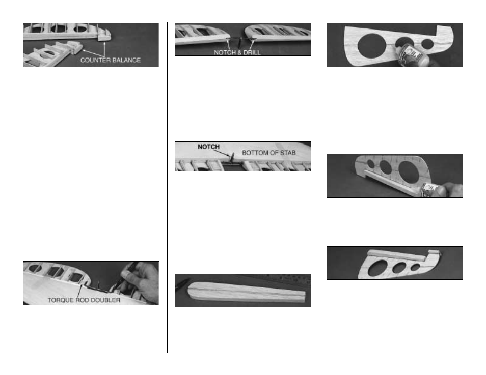
7. Center a die-cut 1/4" balsa Counter-
balance on the LE of the elevator tip as shown
on the plans, then glue it in place. Shape the
front of the block to a radius. Allow
approximately 1/16" clearance on the two
matching edges between the counterbalance
and the notch in the stab.
❏
8. Refer to the photos and the cross sections
on the plans to obtain the shape of the elevator
tips, roots, and ribs. Use a razor plane and
sanding block to "rough in" the shape of the
blocks and ribs. Trial fit the elevators to the stab
for final shaping.
❏
9. Glue a die-cut 1/8" balsa elevator Torque
Rod Doubler to both sides of the Elevator
Bases as shown on plans and below.
❏
10. Tape the elevators to the stabilizer. Hold
the bent 1/8" Elevator Joiner Wire and Horn
up to the elevator and mark the location of the
holes (see the plans for the joiner location).
❏
11. Remove the elevators from the stabilizer.
Drill 1/8" holes in the elevators for the Joiner
wire. Make slots inboard of the holes to allow
the wire to be inset into the elevators. Sand the
Elevator LE to a "V" shape to allow elevator
travel. (See the cross-section on the stab) Test
fit the joiner wire into the elevators. Check to
see that the elevators align with each other
properly. Make adjustments if required.
❏
12. Mar k the location of the Elevator
Control Horn on the TE of the Stab. Remove a
small amount of balsa as shown to allow
clearance for the horn to move freely in both
directions.
BUILD THE RUDDER
❏
1. Glue the two die-cut 3/16" balsa Rudder
LE's together with CA+. Even up the edges with
a sanding block, but save any tapering for later.
❏
2. Draw centerlines on both forward and aft
surfaces of the LE. Draw two parallel lines 1/16"
away from each side of the centerline on the aft
side that will mate with the Rudder Base.
❏
3 . G l u e t h e d i e - c u t 3 / 3 2 " b a l s a F W D
Rudder Base to the die-cut 3/32" balsa AFT
Rudder Base.
❏
4. Align the Rudder Base over the plans and
mark the "Rib" locations on both sides of the
Rudder Base.
❏
5. Hold the Rudder Base centered, at a 90
degree angle, to the rudder LE. Apply CA to
the joint.
❏
6. Center and glue the 1/4" x 3/4" x 1-3/8"
balsa stick Balance Tab LE at the top of the
Rudder Base.
❏
7. Glue a 1/4" x 1/2" x 2-1/2" balsa stick
Rudder Tip to both sides of the top of the
Rudder Base as shown on the plans.
12