Top Flite TOPA0130 User Manual
Page 38
❏
4. Position the die-cut 3/32" Wing Fillet
Formers at the locations shown (dotted line) on
the plans. There are three formers per side.
Glue the formers in place. Sand them flush.
❏
5. Cut two 13-1/2" long Fillet Skins from
1/16" x 3" x 30" balsa sheet. Taper one long
edge to blend with the Fuse. Hold the skin
against the Fillet Formers, even with the fillet
reference line, then trace the outline of the
saddle on the inside surface. Cut away the
excess when marked.
❏
6. Glue the Fillet Skins in position. Lightly
sand the top edge with a sanding block. Apply a
thin layer of Balsa Filler along the
long edge
and also at the forward end to start building up
the LE contour.
❏
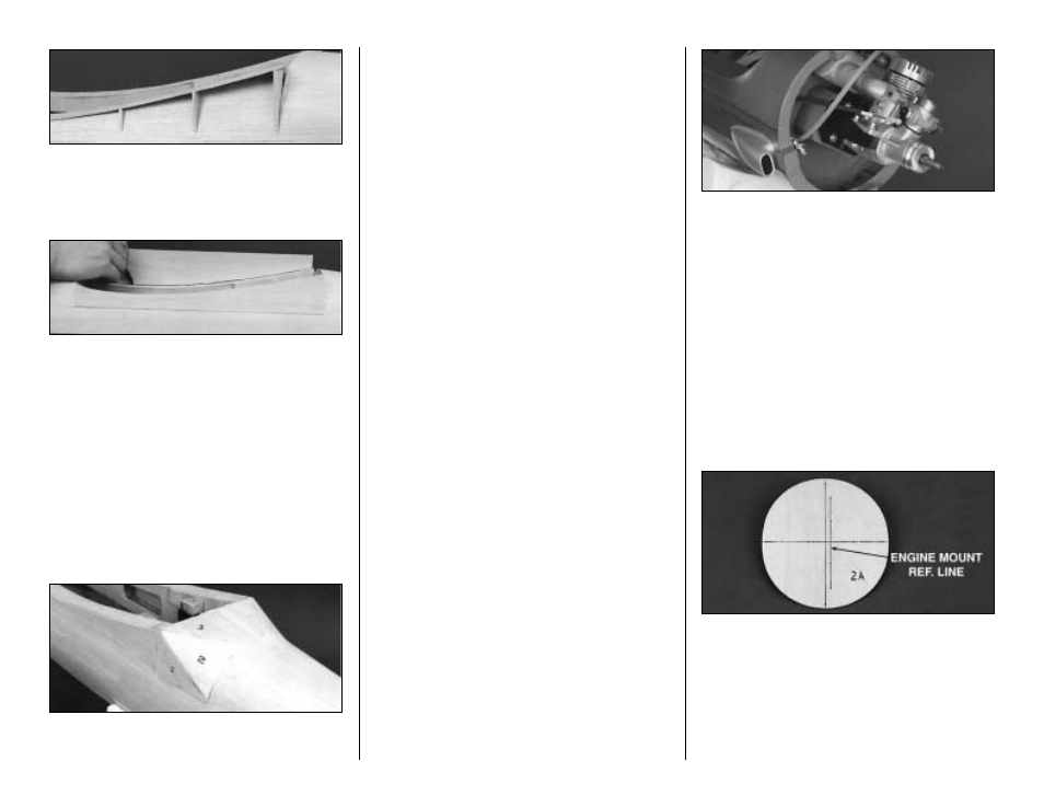
7. Use the templates provided on the plans to
cut two sets of Rear Fillet parts from 1/16"
balsa. Taper (to a sharp edge) the edges of each
part that will contact the fuse sheeting. Glue the
parts to the fuse in the order shown in the photo.
Test fit each piece as you proceed, then use
medium CA along the edges. Lightly sand the
joints, then apply a thin layer of balsa filler to
blend and contour the edges with the fuse.
❏
8. When the filler is dry, sand and blend the
fillet with the fuse. Add extra filler as needed to
obtain smooth curves.
With regards to building, you are on the home
stretch. Get a good night's sleep, then play
hooky from work to do the final assembly steps.
INSTALL THE ENGINE
You have a variety of options when it comes to
engine selection. Our original prototype weighed
8.75 lbs and flew extremely well with an O. S.
.61SF 2-stroke for power. We have also
successfully flight tested the model with an O.S.
1.20 Surpass 4-stroke engine. Due to the high
lift design of the wing, the Texan will have a
tendency to climb as full power is applied when
using a 1.20 4-stroke engine. This condition can
be controlled by adding an additional one
degree of down thrust to the engine.
NOTE: The following sequence
shows the installation of an O. S. .91
Surpass 4 stroke engine. We mounted
all test engines at a 45 degree angle
towards the bottom of the fuse. This
orientation allows the exhaust port of a
2-stroke engine to be connected to a
Top Flite In-Cowl Muffler and to exit
the cowl via the
"scale" exhaust stack.
If you plan on using the Top Flite In-Cowl
Muffler, you will have to do a little sanding on
F-1 to provide clearance for the muffler and to
permit access to the mounting screws. To
strengthen the sheeting in the area that the
muffler (and scale exhaust stack) will exit the
fuse, add some scrap 3/32" balsa between the
stringers, from the firewall to F-1.
❏
1. Draw reference lines through the dots that
are stamped into the die-cut 1/8" Birch ply F-2A
Firewall. The short offset line is to be used for
the centerline of the engine and will allow the
prop to be centered in the cowl opening.
Remember, the Firewall already has been built
with 2 degrees of right thrust.
38