Top Flite TOPA0130 User Manual
Page 29
❏
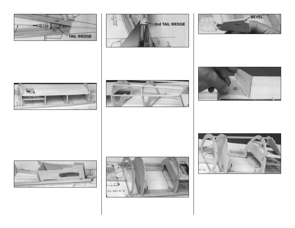
9. Glue one die-cut 1/8" ply Tail Wedge
between the two Main Stringers, against the
wax paper.
❏
10. Glue the two halves of the die-cut 3/32"
balsa Cockpit Deck together. Sand the joint
smooth. Glue the Cockpit Deck to the top of F-4
and F-5 and into the notches in F-3 and F-6.
❏
11. Glue a die-cut 1/8" balsa Stabilizer Saddle
to the top of each Main Stringer aft of F-8. The
forward points of the Saddles fit into the notches
at the top end of F-8.
❏
12. Glue the second 1/8" ply Tail Wedge
inside the top of the Stab Saddle. Use a triangle
to be sure that the assembly is vertical.
❏
13. Cut 3/16" x 3/16" x 36" balsa Stringers
to fit between F-6 and F-8 as shown in the
photo. The top stringers should extend past F-8
by approximately 1/2". To avoid breakage, the
top Stringers should not be glued in place until
after the stab has been installed.
❏
14. Glue F-1 to the Main Stringers where
shown on the plans.
❏
15. Bevel the bottom edge of the die-cut 1/8"
Instrument Panel (IP) to fit flush against the
Cockpit Deck when held at the angle prescribed
by the die-cut Instrument Panel Gauge.
❏
16. Use the die-cut 1/8" ply Instrument
Panel Gauge (IG) to set the angle of IP, then
glue IP to the Cockpit Deck.
❏
17. Cut 8-1/2" from a 3/16" x 3/16" x 36"
balsa stringer. Insert the 8-1/2" stringer into the
notches on the tops of F-1 through IP. About
1/4" of the Stringer should protrude past F-1.
Glue the Stringer to F-3 and IP. Check F-1 and
F-2B with a triangle to make sure that they are
vertical, then glue them to the Stringer.
29