Build the fuselage – Top Flite TOPA0130 User Manual
Page 28
❏ ❏
5. Refer to the plans for Aileron shape.
Use a razor plane and a sanding block to shape
the Aileron. Test fit the Aileron to the wing for
final shaping.
❏ ❏
6. Refer to the plans for the location of the
Aileron Control Horn Block on the bottom of
the Aileron. Glue the 3/8" x 5/8" x 1-1/8" hard
balsa Aileron Control Horn Block in place.
❏ ❏
7. Shape the Aileron Control Horn Block
to match the Aileron contour.
❏ ❏
8. Shape the Aileron LE to a "V" shape to
allow proper Aileron travel. Refer to the plans for
the correct "V" angle.
BUILD THE FUSELAGE
TOP FRAME ASSEMBLY
NOTE: The 1/8" die-cut plywood
for mers are stamped only with the
necessary portion of their name. For
example, F-2B is stamped 2B.
IMPORTANT: All formers must be
installed with the stamped ident-
ification number facing
forward. Drill
3/16” holes through each of the
punch marks on formers 4 – 8 before
proceeding.
❏
1. Pin the top view of the Fuselage plan to a flat
building surface, then cover it with waxed paper.
❏
2. Align and pin the die-cut 1/8" ply Forward
Crutch to the plans.
The angle of the forward
edge is designed to provide the correct amount
of right thrust for the engine.
❏
3. Pin the 3/8" x 1/2" x 40" Shaped Main
Stringers to the plans on each side of the
crutch. Glue them to the crutch with thin CA. The
Shaped Main Stringers must be positioned with
the 1/8" groove closest to the plans, facing
outward. Leave excess material extending
beyond F-1 and also at the tail for trimming to
size later. HINT:
You might find it easier to only
pin the forward end of the Stringers next to the
Crutch, then bend and pin the Stringers to match
each former as you proceed towards the tail.
❏
4. Glue F-2B to the forward edge of the
plywood crutch.
NOTE: Use a small triangle to hold
ALL formers vertical while gluing.
Any small warps or twists will be
taken out when the 3/16" stringers
are glued in later.
❏
5. Glue F-3 and F-4 to the Main Stringers.
F-3 is also glued to the aft edge of the crutch.
❏
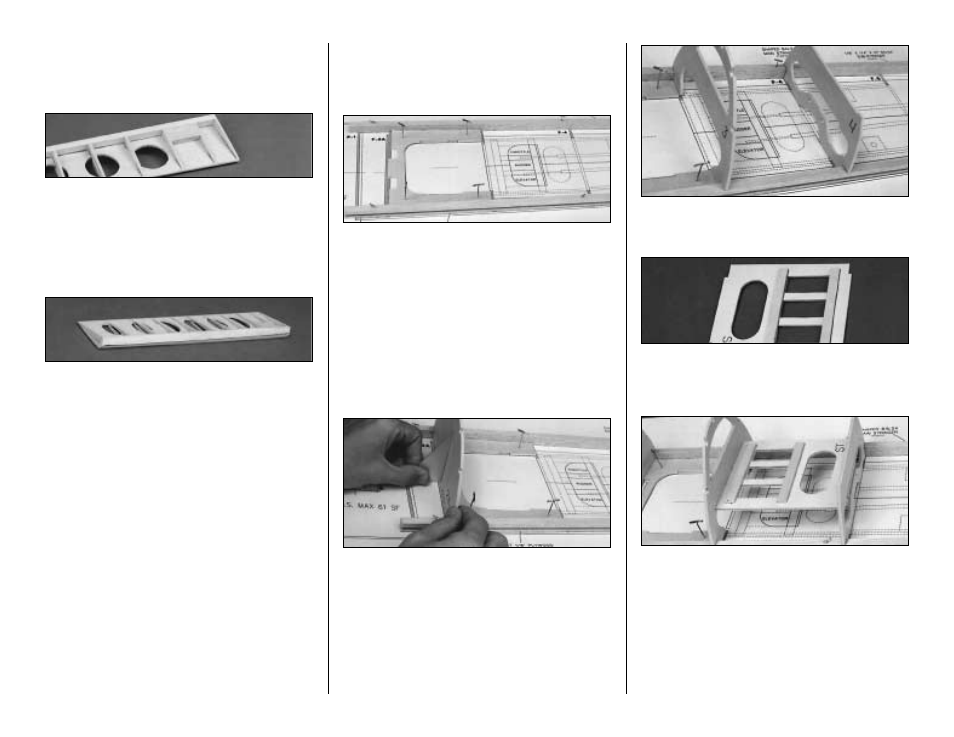
6. Cut two 1/8" x 3/8" x 3-3/4" Servo Rail
Doublers from left-over die sheet ply. Glue the
rails to the servo tray as shown in the photo.
❏
7. Glue the Servo Tray, with the doublers
facing up, between F-3 and F-4. The Servo tray
is notched to fit into the underside of the
formers.
❏
8. Glue F-5 through F-8 into place along the
Main Stringer. As before, keep the assembly
centered, and all formers vertical.
28