Top Flite TOPA0130 User Manual
Page 45
HINGE THE ELEVATOR
❏ ❏
2. Test fit the elevators to the stabilizer
with all of the hinges and the wire joiner in
place. Make sure the elevators are both set at
the same angle. Make adjustments if necessary.
❏ ❏
3. Work a generous amount of 30-minute
epoxy into the wire joiner holes in the elevators.
❏ ❏
4. Work the elevator hinges into the stab
and, as you do this, insert the wire joiner all the
way. Wipe away any excess epoxy. Glue the
hinges in place using 4-6 drops of thin CA on
both sides of each hinge.
HINGE THE AILERONS AND
RUDDER
❏
5. Pack 30 minute epoxy into the tail wheel
hole in the rudder, then install the Rudder in the
same manner as the Elevators.
❏ ❏
6. Hinge the Ailerons using the same
technique as the Elevators.
❏ ❏
7. Flap hinge installation is covered in the
Flap Fitting section on page 41.
THERE SHOULD BE NO HINGE GAP
FINAL CONTROL HARDWARE
HOOKUP
❏ ❏
1. Epoxy the 5/16" x 3/4" x 7/8" hardwood
Flap Servo Mounting Blocks to the die-cut
1/16" ply Flap Servo Hatches. Install the flap
servos as shown in the photo and on the plans.
Fish the servo wires through to the opening at
the center of the wing, then plug them into a "Y"
cord. Before permanently screwing the servo
hatches in position, hook up your radio and set
the flap servos' throws.
❏ ❏
2. Install the flap and aileron horns in line
with the pushrod exits as shown on the plans.
Drill 1/16" holes into the control surfaces at the
proper horn locations, then soak the holes with
CA glue. Screw the horns in place with #2 x 3/8"
Sheet Metal Screws.
❏ ❏
3. Hook up and adjust the aileron and
flap linkages. Two .074 x 4" Threaded End
Rods and Nylon Clevises are supplied to
make the flap pushrods. The flap pushrods
may be connected to the ser vos using Z-
bends, or solder-on clevises (not included.)
Refer to the Control Surface Throws section
for movement recommendations.
❏
4. The Rudder is connected using a Small
Control Horn (cut down to two holes) and a
Nylon Clevis. Refer to the plans for the proper
location. Mark the location of the horn and drill
two 1/16" pilot holes par t way through the
rudder. Thoroughly soak the holes with CA. Put
a drop of CA on the back of the horn and screw
the horn onto the rudder with two #2 x 3/8"
Sheet Metal Screws.
❏
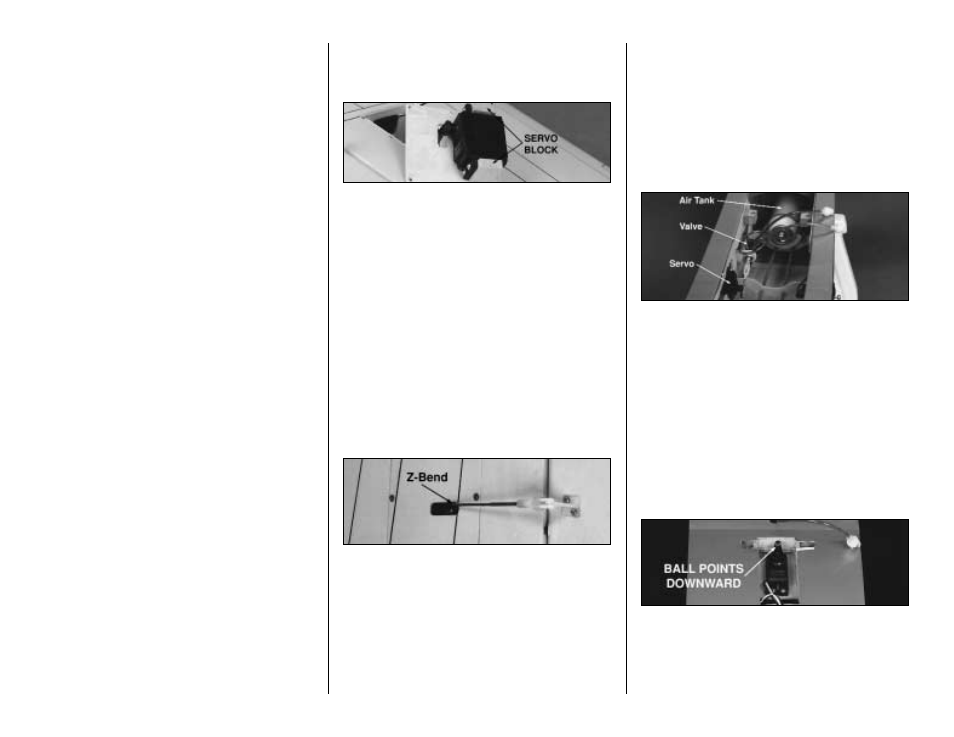
5. The retract air valve, tank, and servo
installation can be seen in the photos above and
below.
We found that a micro (Futaba #133)
servo worked well for actuating the air valve.
The tank fits in the built-in cradle in formers F-5
and F-6. It can be secured with two #2 x 3/8"
screws and a rubber band (not supplied) or
silicone glue.
❏ ❏
6. Solder-on threaded couplers and nylon
clevises are recommended for internal elevator
and rudder servo hookups. Refer to the photos
and plans for proper servo and horn orientation.
❏
7. The aileron servo hookup can be seen in
the above photo. The aileron servo is fitted with a
2-56 Threaded Ball Link connector that points
downward toward the dual aileron connector.
45