Top Flite TOPA0130 User Manual
Page 22
❏ ❏
13. Rough cut the hatch openings on the
inside of your guide holes, then use a 1/16" ply
Hatch Cover to mark and cut the full size
opening.
Remember, it's faster to enlarge a hole
that's too small than to shrink one that's oversize.
❏ ❏
14. If you will be installing retracts,
remove enough mater ial to install the
mechanism and air cylinder, but leave final
fitting of the gear struts and wheels until later.
❏ ❏
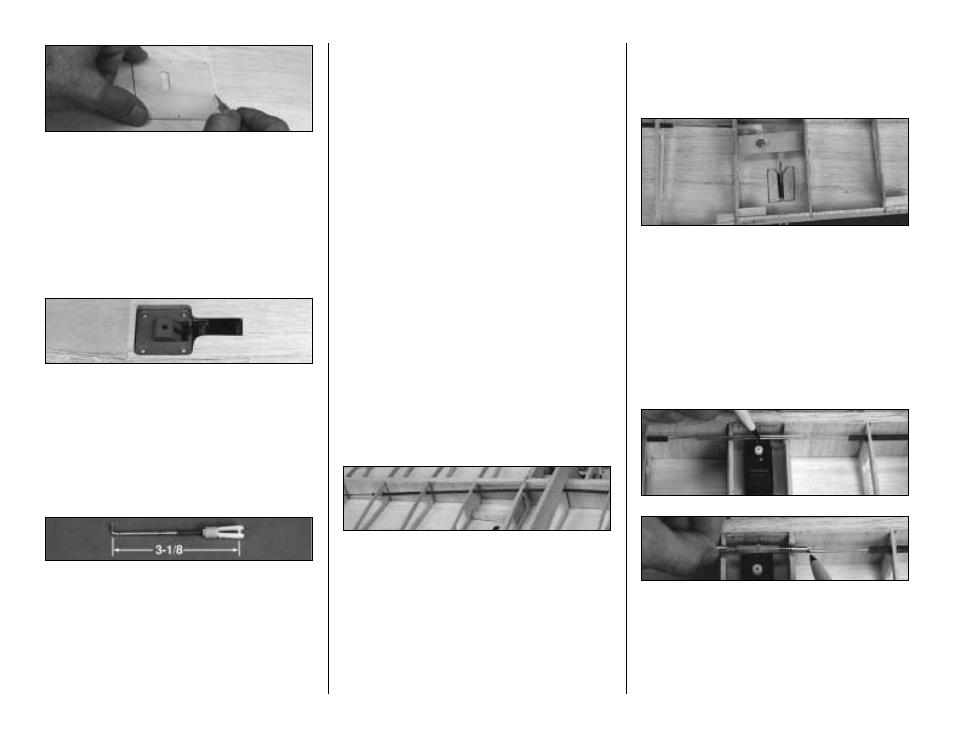
15. Screw a Nylon Clevis onto a 4" Wire
Pushrod. The threaded por tion of the wire
should be flush with the inside edge of the
clevis. Make a 90 degree bend 3-1/8" from the
clevis pin. Cut off the excess wire, 1/4" past the
bend. Make a second pushrod in the
same manner.
❏ ❏
16. Insert the aileron pushrod through
the access hole in the skin and poke it through
the bellcrank from the top. Hint:
Use a 5/64"
drill bit to enlarge the hole where the aileron
pushrod will connect with the bellcrank. Attach
a Nylon Faslink to secure it in place. Repeat
this step for the other wing panel. If necessary,
hollow out a small indentation on the underside
of the ply to prevent the Faslink from catching.
❏ ❏
17. Cut the two 24" Plastic Outer
Pushrod Tubes to a length of 15-1/2". After
roughening the outer surface of the tubes with
sandpaper, push them through the 3/16" holes
that you drilled earlier during construction. Refer
to the plans for exact location, but generally they
run from W-2 to W-9. When positioned, spot
glue them to each rib with Medium CA.
❏ ❏
18. Screw a Nylon Clevis onto the
threaded ends of two 36" wire pushrods. As
before, the threads need to be into the clevis
about 1/4", or flush with the inside opening. Cut
the pushrods down to 22-1/2". Cut ten 3/16"
lengths of inner plastic pushrod tube, then slide
them onto the wire as shown on the plans. If they
are too loose, apply a drop of CA to secure them
in place. If too tight, cut them a little shorter.
Carefully inser t the pushrod wires into the
tubes from the W-11 ribs towards the center.
Hook-up the clevises to the bellcranks and
check for free movement.
❏ ❏
19. Position the aileron (outer) pushrod
clevis pin approximately 1/16" behind the TE
and tape it in position against the underside of
the wing. The bellcranks should be neutral.
Repeat this step for the other wing panel.
❏
20. Screw Threaded Brass Couplers all the
way into both ends of a Nylon Dual
Aileron Coupler.
❏
21. Hold the pushrods together at the center
of the wing and draw a line across both
pushrods at the center of the servo opening.
Hint:
It helps to drop a servo into position to
help with this alignment procedure. Hold the
Aileron Coupler on the pushrods with the Ball
22