Top Flite TOPA0130 User Manual
Page 39
❏
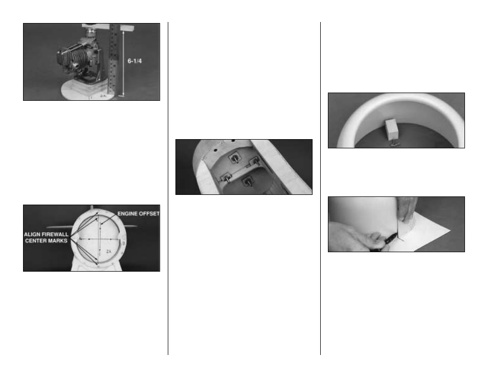
2. Bolt your engine to an engine mount, then
position it on the F-2A Firewall. Add plywood
shims, as required, to position the propeller
backplate 6-1/4" from the Firewall (this
applies to all engines).
❏
3. Glue the plywood shims together. Center
the engine mount on top of the shims and mark
the mounting hole locations. Center the mount on
F-2A using the offset line for horizontal alignment.
Drill the mounting holes with a 5/32" bit.
❏
4. Center F-2A on F-2B/F-2C. Use the
center joint between the formers and the two
punch mar ks on the top and bottom for
alignment. Note: When doing this alignment,
make sure that the Fuse is right-side-up and
that the offset line is to your right (or the
pilot’s left). Use the vertical centerline, not
the offset line, to align the Formers (refer to the
firewall drawing on the fuse plans).
❏
5. Hold F-2A in position, then mark the
mounting holes on F-2B/F-2C. Drill these holes
with an 11/64" bit to accommodate the blind
nuts. Check inside the fuse to see where the
holes are in relation to the blind nut cutouts on
the forward crutch. Enlarge the cutouts, if
necessar y, to accommodate the 1/8" ply
Firewall Backups.
See photo for step #7.
❏
6. Locate the four pre-cut 1/8" x 3/4" x 3/4"
Birch ply Firewall Backups. Drill an 11/64" hole
in the center of each. Insert the supplied 6-32
engine mount blind nuts into each ply Backup,
then gently seat them with a hammer.
❏
7. Insert the supplied 6-32 x 2-1/2" engine
mount screws through the mount, spacer shims,
and firewall to check the fit. Screw the blind nuts
onto the mounting screws from inside the fuse.
Glue the blind nut assemblies in position on the
inside of the firewall with CA.
Hint: work some
petroleum jelly into the threads to prevent any
stray glue from causing problems. Use a cut-off
wheel and Dremel tool to trim excess screw
length.
❏
8. Once the blind nuts are installed, remove
the engine mount assembly. Coat the back side
of F-2A with 30-minute epoxy, being careful to
stay at least 1/4" clear of the screw holes. Align
F-2A with F-2B/F-2C, then install the engine
mount with all four screws to
clamp F-2A in
position while the epoxy cures.
FIT THE COWL TO THE FUSE
❏
1. Make a simple tool to mark the inside of
the cowl by inserting a T-pin through a small
block of balsa, 3/16" above the work surface.
3/16" is the distance the cowl will extend over
the Fuse sheeting.
❏
2. Work on a flat surface. Hold the marking
tool with the point against the inside of the
cowl, then rotate the cowl to scribe an even
line around the inside circumference.
❏
3. Center the cowl over the Baffle Template,
then mark the four centerline positions around
the perimeter of the cowl. These four points will
be your mounting block locations.
❏
4. Measure and mark exactly 7/16" from the
rear edge of the cowl at each of the four points.
Hint: Use the same gadget that you made in
step #1, just reposition the T-pin to 7/16".
❏
5. Drill a 1/8" hole at each of these locations.
39