Top Flite TOPA0130 User Manual
Page 17
❏
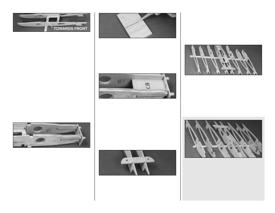
3. Work the die-cut 1/8" ply Aileron Servo
Tray into the slots in the W-1 ribs where shown
on the plans. The punch mark on the tray must
be positioned toward the leading edge. When
installed correctly, there should only be a 1/16"
gap between the edge of the Servo Tray and the
Spar. This gap will allow a Shear Web to be
inserted later. When satisfied with the alignment
of the ribs and the Servo Tray, glue everything in
place with CA.
❏
4. Slightly round one end of both 1/4" Wing
Dowels. Test fit the Wing Dowels into the slots
in both W-1 ribs with the round end facing out. If
needed, lightly sand the openings for a good fit.
Slide the die-cut 1/8" ply Dowel Jig over the
dowels to set the correct spacing between them.
Use 6-minute epoxy to glue the Dowels into the
slots. During this step don't worry about which
end of the Dowel Jig is facing the work bench.
You are only setting the horizontal spacing.
❏
5. Glue the two die-cut 1/8" balsa Center
Brace (CB) squares together along one edge.
The grain must run across the narrow dimension.
❏
6. Check the fit of the Center Brace between
the dowels. Sand the edges for a snug fit. Use 6
minute epoxy to glue it to the dowels with liberal
fillets of epoxy around the joints. When the
epoxy has cured, remove the dowel jig but save
it for use during the wing sheeting process.
❏
7. Glue the two die-cut 1/8" ply Wing Bolt
Plates together with CA. Slide the joined Plate
through the slots in the aft end of the W-1 ribs
but don't apply glue yet.
IMPORTANT
THE STEPS PRINTED IN THE SHADED
BOXES ARE FOR BUILDING YOUR AT-6 WITH
RETRACTABLE LANDING GEAR.
SKIP THE
SHADED INSTRUCTIONS IF YOU WILL BE
INSTALLING FIXED GEAR.
❏
8. (For FIXED GEAR only) Pin Rib
assemblies W-2 , W-4, and W-5 on the Spar. Be
sure the 2F, 4F, and 5F Ply Doublers are facing
the correct direction. Make sure that the jig tabs
are in contact with your work surface and that
the tips of their trailing edges are aligned. Use a
small triangle to hold the ribs vertical, then glue
them to the Spar.
❏
8. (For RETRACT GEAR only). Pin Rib
assemblies W-2, W-4, and W-5 on the Spar. Be
sure that the 4R and 5R Ply Doublers are
facing the correct direction. Make sure that the
jig tabs are in contact with your work surface
and that the tips of their trailing edges are
aligned. Use a small triangle to hold the ribs
vertical, then glue them in place.
17