Top Flite TOPA0130 User Manual
Page 19
❏
20. NOTE: perform this step regardless of
landing gear configuration. Glue the die-cut
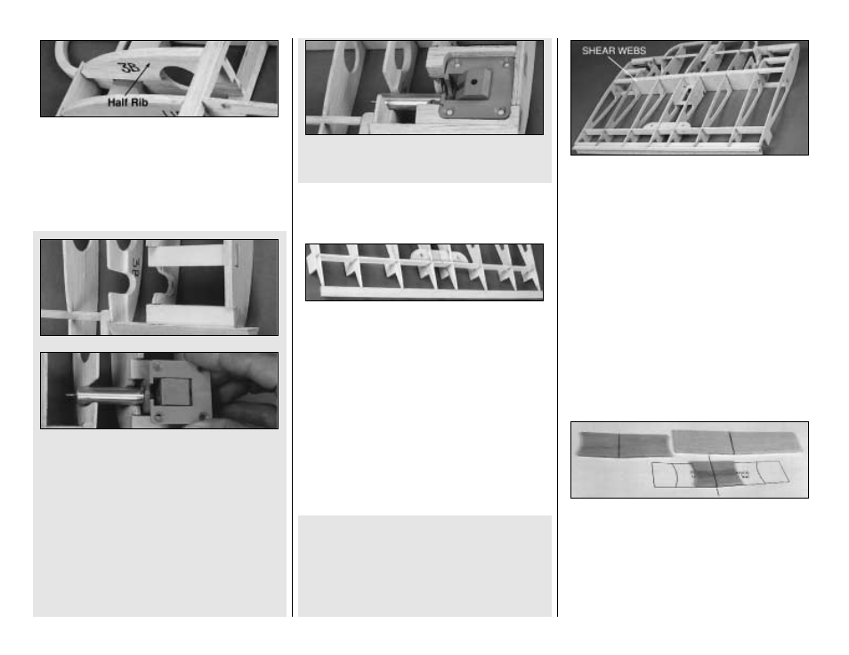
1/8" balsa Half-rib W-3B to the top half of W-3
as shown on the plans. Make sure that it's flush
with the contour of W-3.
❏
21. (Retract Gear) With the center panel
pinned to the work surface, insert the two 1/4" x
1/2" x 2-1/2" ply Landing Gear Rails into the
notches in ribs W-4 and W-5. Test fit the retract
mechanism (without the struts in place) and
make any adjustments required for a good fit.
Don't cut out the wheel wells in W-2 just yet;
we'll get to that after sheeting the bottom of the
wing. When everything fits well, use 30-minute
epoxy to glue the Rails in position. Be sure that
the outer edges of the Rails are flush with the
outside surface of the W-5 ribs.
❏
22. Use scrap balsa to build a supporting
base for the sheeting, as shown in the photo.
❏
23. Do this step if you are NOT installing
operational Flaps.
Tr ue-up the aft edge of the r ibs with a
straightedge and T-bar sander. Cut the 1/2" x
24" tapered balsa Trailing Edge to 17", then
glue it to the ribs. The TE should be centered on
the aft edges of the ribs and should be aligned
as in the cross-section with the top and bottom
of the ribs. Make sure all the jig tabs are
contacting the table. A metal straightedge can
be placed on the structure over the jig tabs to
hold them down evenly during this step.
For operational flaps, perform steps 1 - 10 on
page 15-16, applying the same techniques to
the center panel. Substitute 18" pieces
where 12" lengths are specified. Note: The
next photo shows the ply TE installed, but
the ribs have not yet been trimmed out.
❏
24. Glue 1/16" balsa Shear Webs to the
front and rear of the center panel main Spars
between all ribs except W-4 and W-5.
❏
25. Trim the Spars, LE, and TE flush with the
outside edges of the W-5 ribs. Lightly sand the
top, bottom, and ends of the center panel to
blend the ribs with the Spars and to remove any
excess glue.
PREPARE THE POLYHEDRAL
BRACES
❏ ❏
1. Position the 1/8" ply Polyhedral Braces
over the sketch on the plans. Look carefully at
each piece and you will notice that one end is
slightly tapered. This is the end that plugs into
the outboard panel. After you align each piece
over the drawing, mark an index line on each part
as shown, then extend it around to both edges.
19